Update...
Spent all day Sunday wiring. Even though my pictures don't really show the work. I was very picky about where the wires ran and being organized.
So on the engine harness I started with the 3 wires running to the starter. Two reds and a purple. One of the reds was a heavy 8 gauge that runs to the Alternator. The other red and purple went inside to the starter switch. I routed them all together and close to the block to keep them away from the header and put 3/4" convoluted tubing around them. I would have run 1/2" but it wouldn't contain the 2 big fusible links on the red wires.
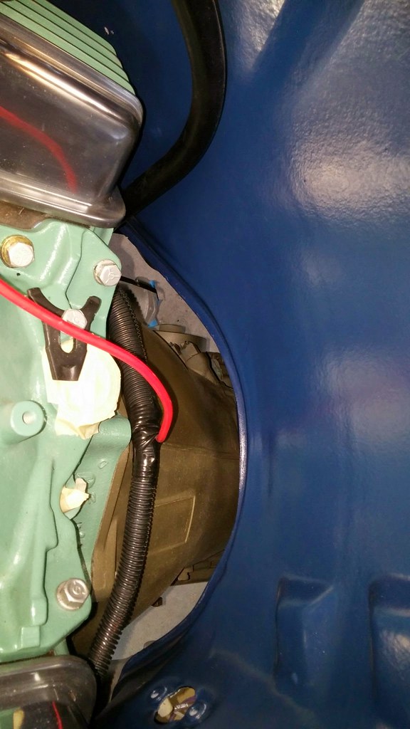 20150517_153325
 by
bjohnson388, on Flickr
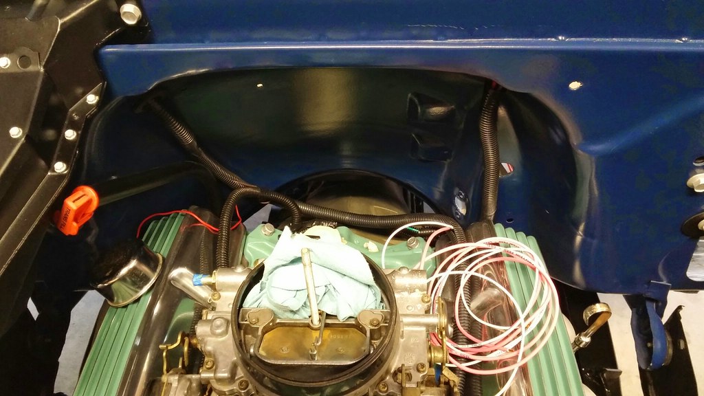
So I came across the back of the engine and the big 8 gauge wire came out to run up to the Alternator. I ran the other two to this top firewall grommet as I all I had planned for here is the oil pressure line and it is very close to the plug on the dash harness. I ran 1/2' convoluted tubing for these 2 wires down to the 3/4" and taped together.
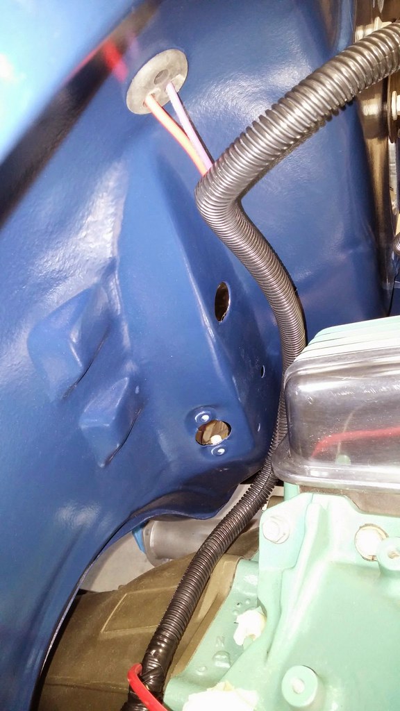 20150517_153343
 by
bjohnson388, on Flickr
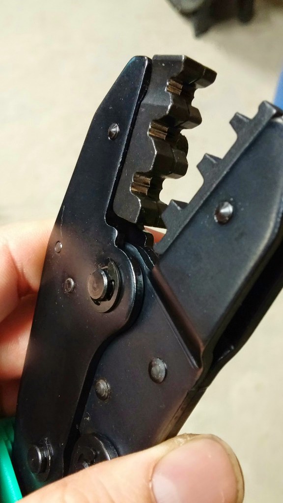
Here are those 2 wires. My first and second crimps. Not too bad. The Crimper was adjusted a little tight so I loosened it one notch.
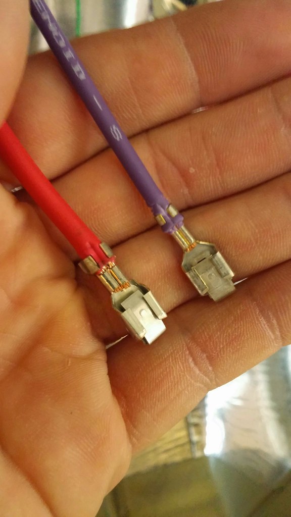 20150517_161447
 by
bjohnson388, on Flickr
Here is the big red 8 gauge wire along with the brown wire from engine harness running to alternator. I used some 1/2" rubber insulated clamps bolted to the valve covers to hold in place. I also ran the hot wire for the electric choke in this tubing which is 3/8" back up to the firewall. I will crimp a male terminal on it and insert it into the engine harness. I removed 2 wires from the engine harness plug I didn't need. The Oil sending unit(since I have gauges) and the other was for alternate temp w/cold light.
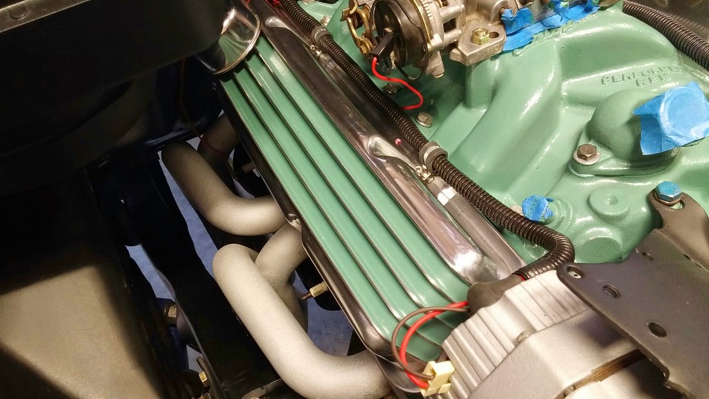 20150517_182226
 by
bjohnson388, on Flickr
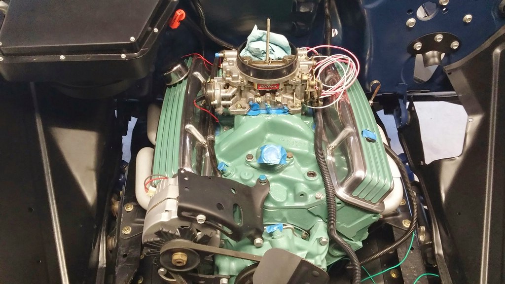
So in this pic you can see the engine harness coming down from the left and the pink and white wires are for the ignition and I ran the green temp wire behind the driver valve cover and down the side. Going to attach it with rubber clamps as well to the valve cover.
 20150517_182207
 by
bjohnson388, on Flickr
In this pic you can see the green wire on the driver side. I didn't cut any of the tubing yet it looks like a mess.
 20150517_182156
 by
bjohnson388, on Flickr
I pulled the MSD box, Distributor, coil, and wires from my Caprice to run in the 64'. I painted the cap black to look more like stock. I need to paint the coil black as well and clean up the wires. I originally was going to mount the box under the dash, but have since decided to either mount it under the battery tray or on the other side of the core support behind the battery. Will have to mock that up and see what fits best. The reason I choose to not mount it inside was because I would have to run 4 wires through firewall and I don't want to drill any holes.
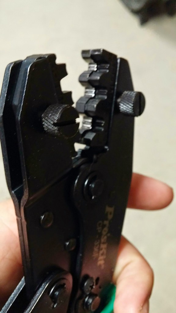
One last thing. Here are the crimpers I bought. They work really well except for that 8 gauge wire was to big for them so I had to crimp it best I could and them some solder to make sure it was solid.
 20150517_113055
 by
bjohnson388, on Flickr
 20150517_113042
 by
bjohnson388, on Flickr