Quote:
Originally Posted by Palf70Step

I know the feeling and I only have 2 locations!  |
I do a lot of walking between buildings throughout the day.
Quote:
Originally Posted by TennesseeZ
Sweet! Ya gonna invite us all up to the porchwarming lol?
|
If anyone is ever around my area and wants to stop by for a look-see at what I got going on, just PM me and come on over. I actually have enough room out here to host a small event but being 100 miles from any major city keeps things inconvenient for most people.
Quote:
Originally Posted by Dieselwrencher
Very nice work on the porch! Ours is settling in on the corners and I really have been considering building one myself too. Post more pics as you go. I'd like to check it out.
|
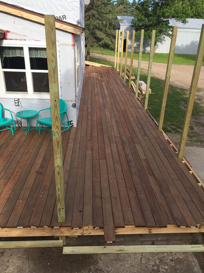
You know you're always welcome to stop by. Almost finished the deck boards. Just have the last row to do and trim off the edges. It's about 54' long, 6' short of a bowling lane.
Quote:
Originally Posted by Orange67
Wow. Gotta tell you, I just spent the last week reading through your thread. Awesome story man. Love all the pics, and places you've seen. Nice place you've got there too.
|
Thanks, glad you enjoyed it.
I'm going to make an attempt to get another post up before the next road trip. First a little background. I'm from MN originally but the navy had me around the country for the 6 years I was in and during that time I got married to someone from elsewhere. After I was discharged I spent some time in Idaho, then came back to MN for a job, hated it, so I kept looking and eventually I became a boiler inspector. That took me to the NW part of the state and I really liked it up there, but the wife didn't. So another change of scenery came but neither of us was really happy there. She said it would be ok to go back to MN and I found an opportunity to be an authorized inspector, which is a 3rd party inspector hired by a fabrication shop that's building ASME stamped boilers or pressure vessels. That's what brought me to the current location back in 2001.
The shop I worked at built air compressors, which is basically line assembly work and as an inspector, it really can't get much more boring. I got laid off when the shop lost one of it's major customers and wanted to change to a half time contract. It sucked at the time to lose my job but it was really a blessing because eventually I found a much better position, got a ton of new experience and really opened a lot of doors for me. It made me a better all around inspector. Then I got laid off again in 2015.
And to bring this little story full circle, I'm working for the same company now that laid me off back in 2003. And since I'm still holding the commission and endorsements to do shop inspections they ask me to fill in once in a while in that same air compressor shop. So today I'm going to show you how that tank was made that's out in your garage.
But first, check out the welders vending machine...

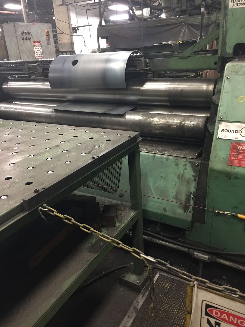
They start with a flat sheet of steel. This is actually a pretty strong grade, rated at a fairly high tensile strength. That way they can use thinner metal and still have a high pressure rating. This is not the cheap stuff. The sheets are delivered cut to the appropriate size and put through a press that punches out the holes for nozzles.

The plate is rolled into a shell.
The shell long seam is welded using a sub-arc welder. This gives full penetration in a single pass and is a very strong weld.
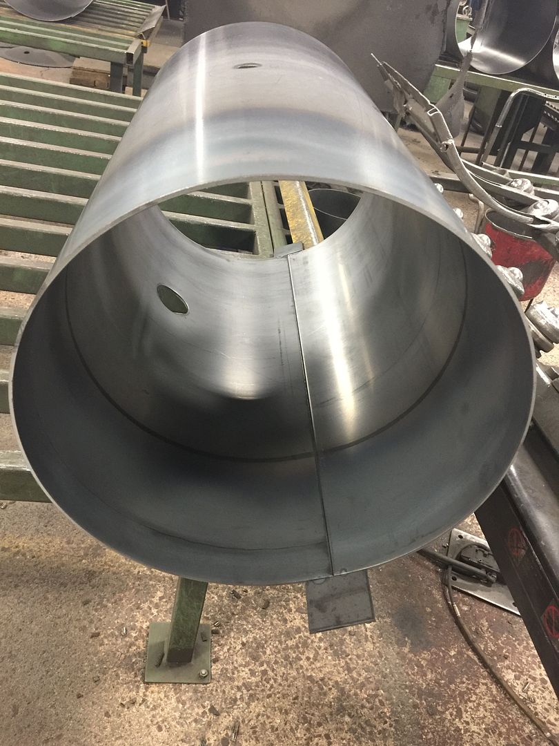
While that's being done the heads are also being prepared. They are delivered preformed with a slip in flange that slides into the shell. That particular weld joint is called a joggle joint, but I'm getting ahead of myself a bit.

There are nozzles in both heads and those holes are also punched out in a small press.
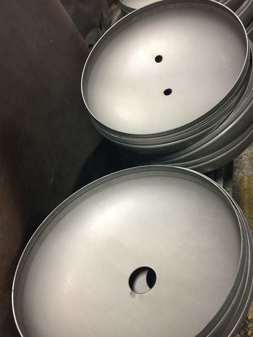
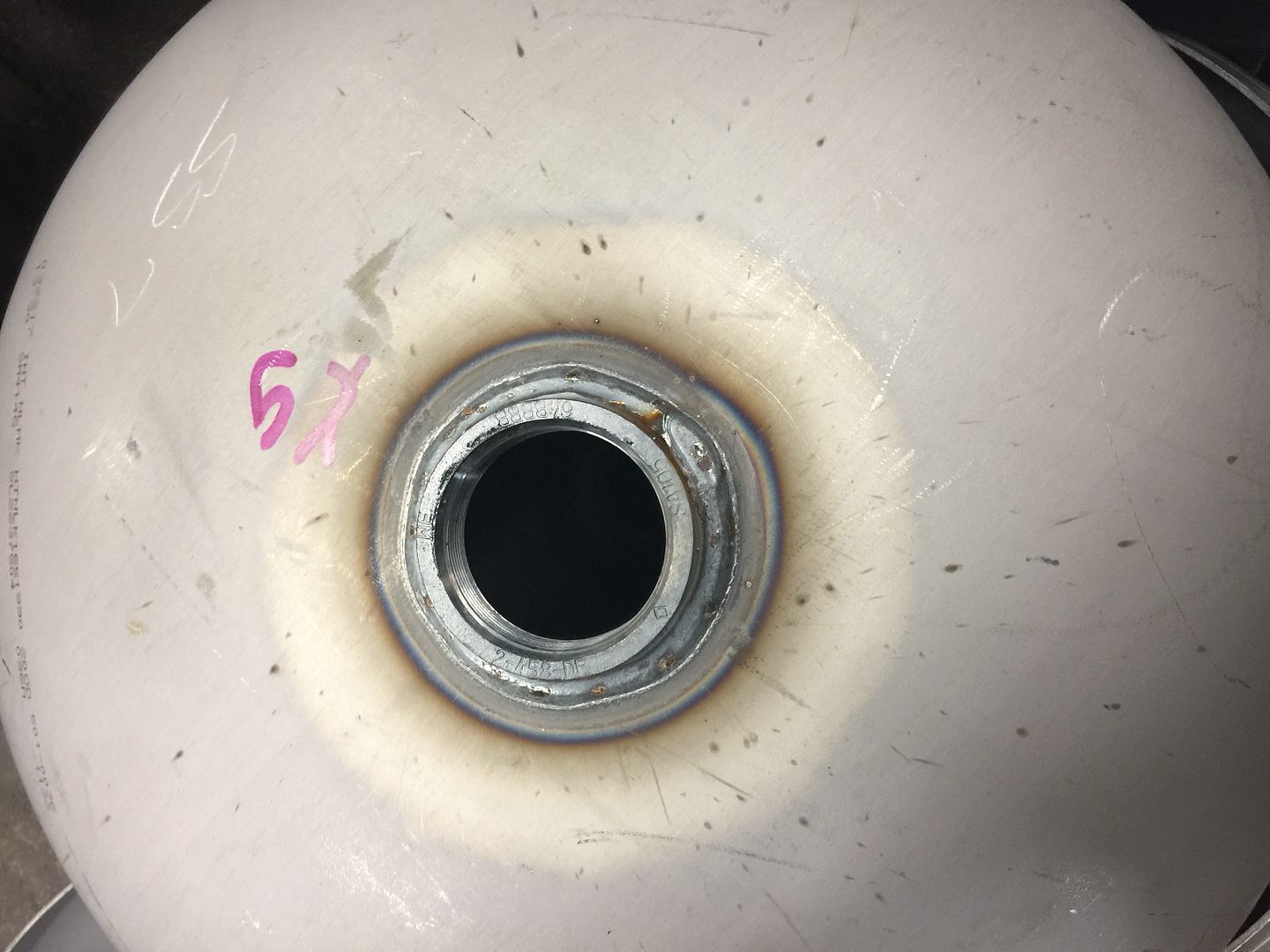
Bottom head with the drain plug nozzle welded in...
Top head with the compressor discharge line connection and a nozzle for a relief valve...

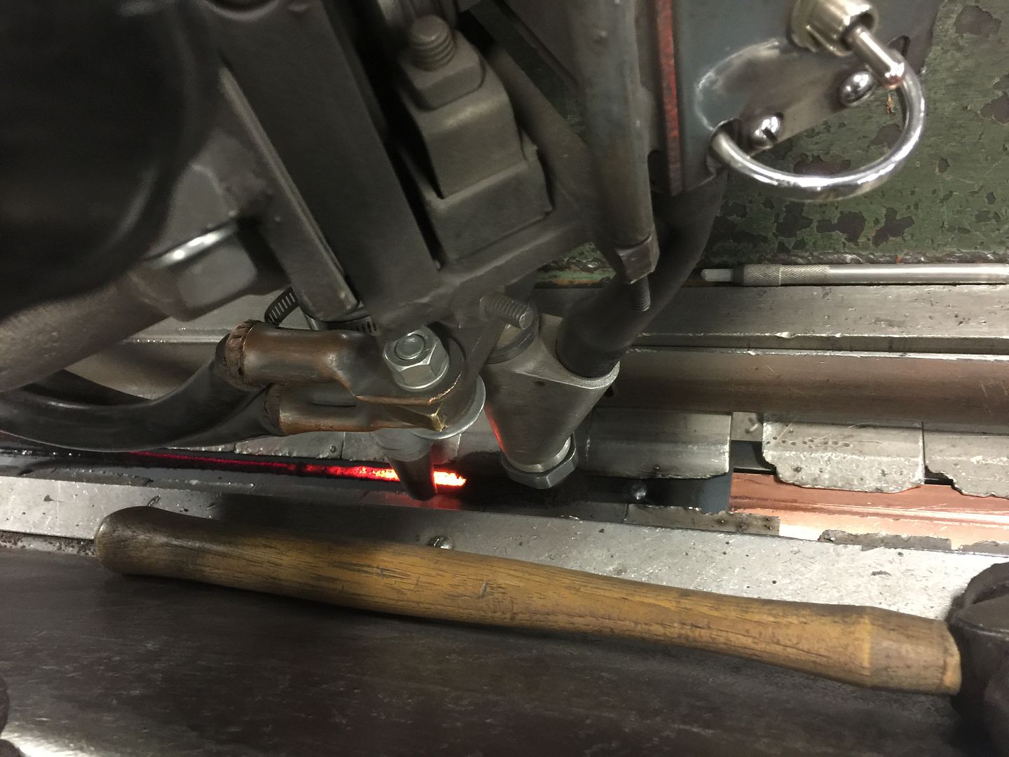
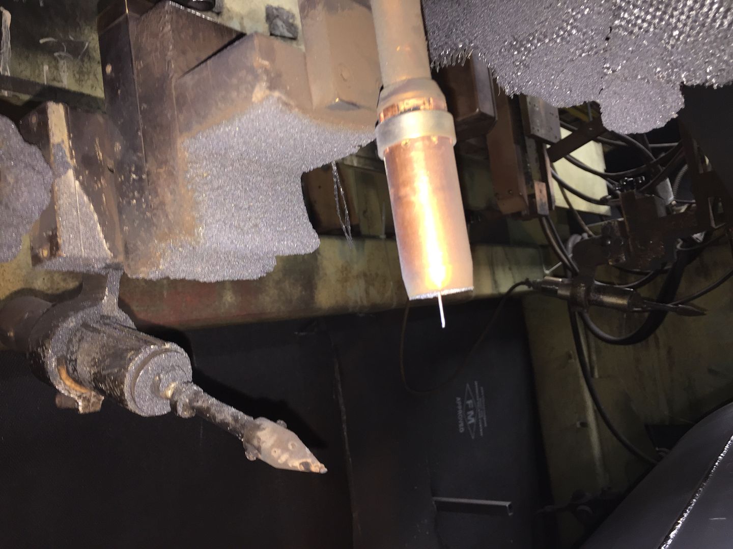
This is what the welder looks like that welds the nozzle bungs in. It's a MIG welder that goes in a circle. Nothing too fancy.
Then the heads are fit into the shell and sent to the circumferential welder.
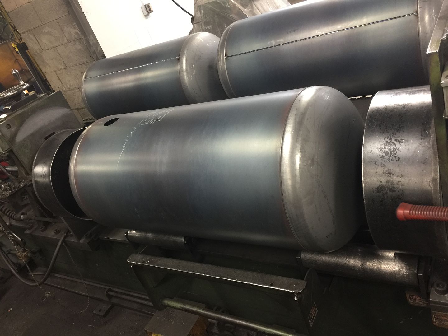
Both heads are welded in at the same time. It's a machine with 2 MIG welders and it rolls the tank around automatically for a nice even weld. The joggle joint provides backing for the weld to ensure full penetration.

After that, the shell will get it's nozzles welded in using the same type of machine as on the heads.
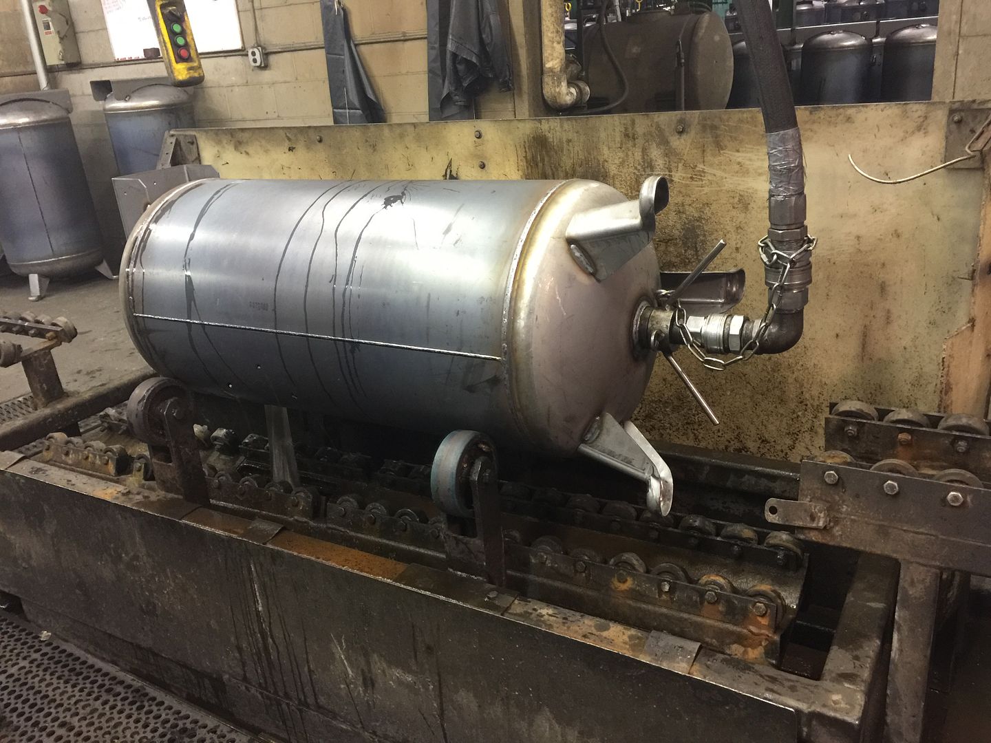
Then the tank goes to the next station where a welder puts on the feet or supports and the mount for the compressor and motor. He also tacks on the ASME nameplate that shows who built the tank and it's ratings. If you look at yours you will see the minimum thickness of the shell and heads on it to give you an idea of what's containing that pressure. That's done by hand using a MIG welder.

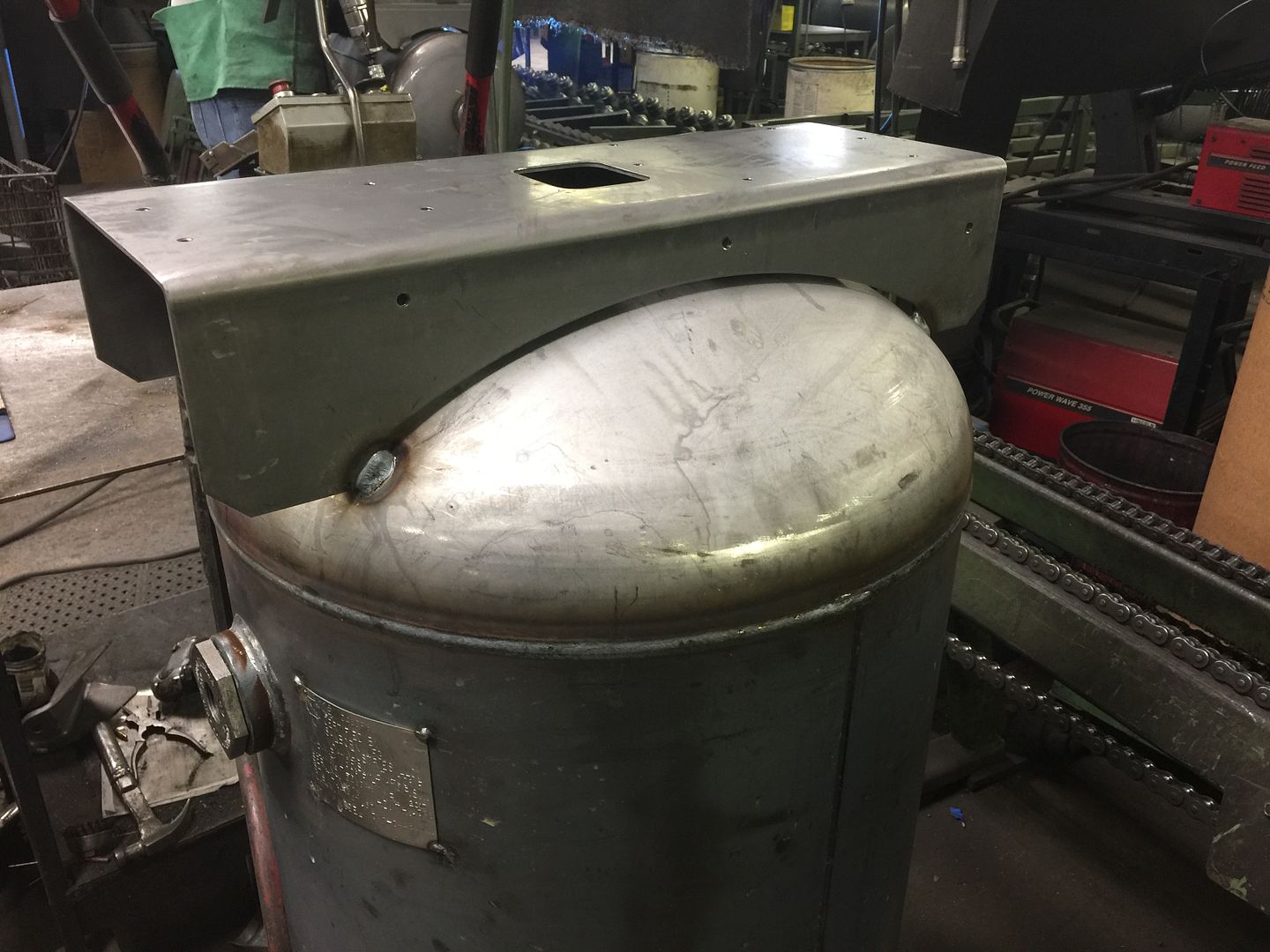
The welding is done at this point and the tank goes to final inspection and gets hydrostatically tested.
If it passes it gets hung on an overhead conveyor where it goes through a powder coating system. When I was the full time shop inspector they were just getting that powder coating system going. They sprayed every tank with paint by hand before that point.
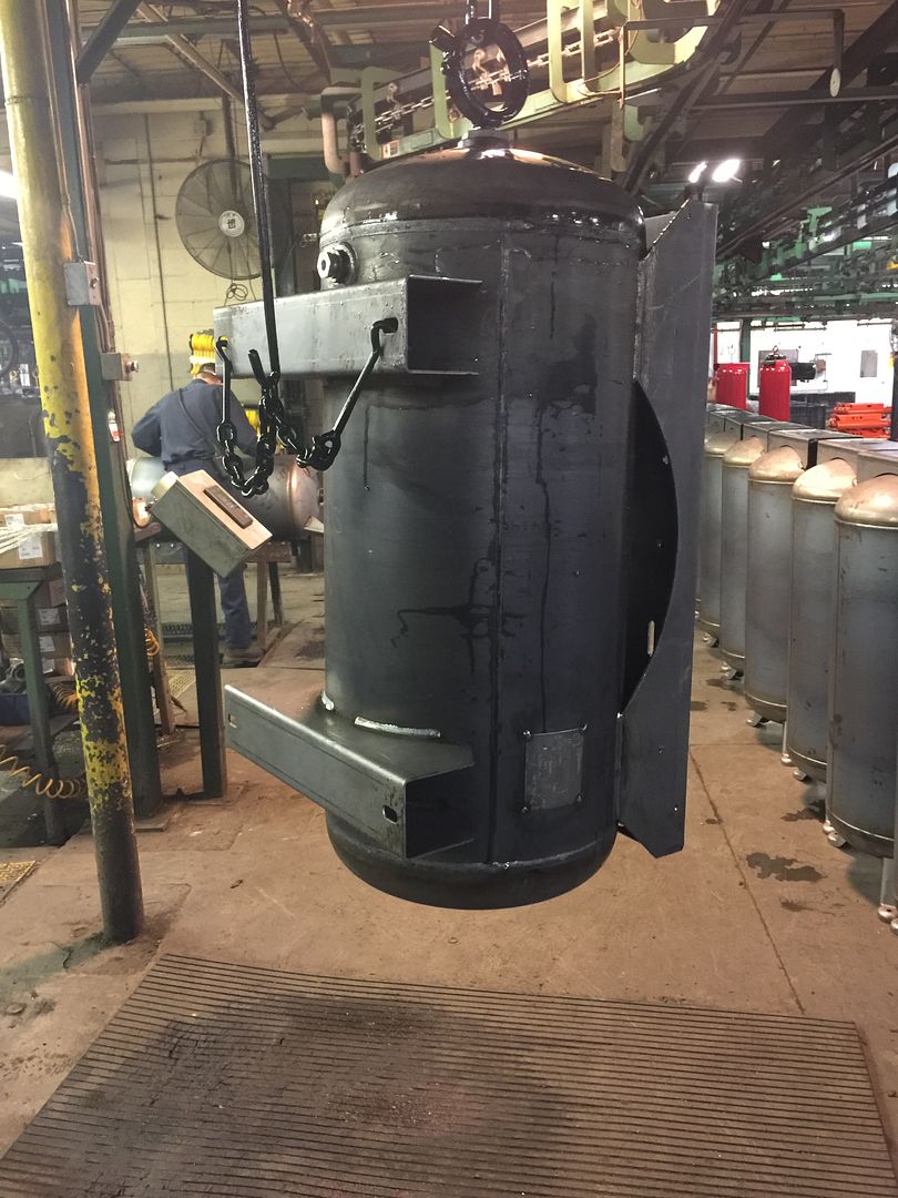

The nice shiny tanks then go to the assembly lines where the pumps, motors and controls and stickers are put on, it gets boxed and sent to the warehouse.
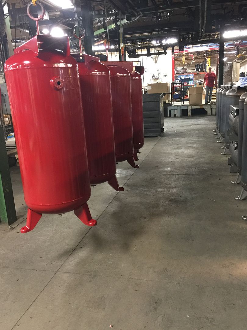

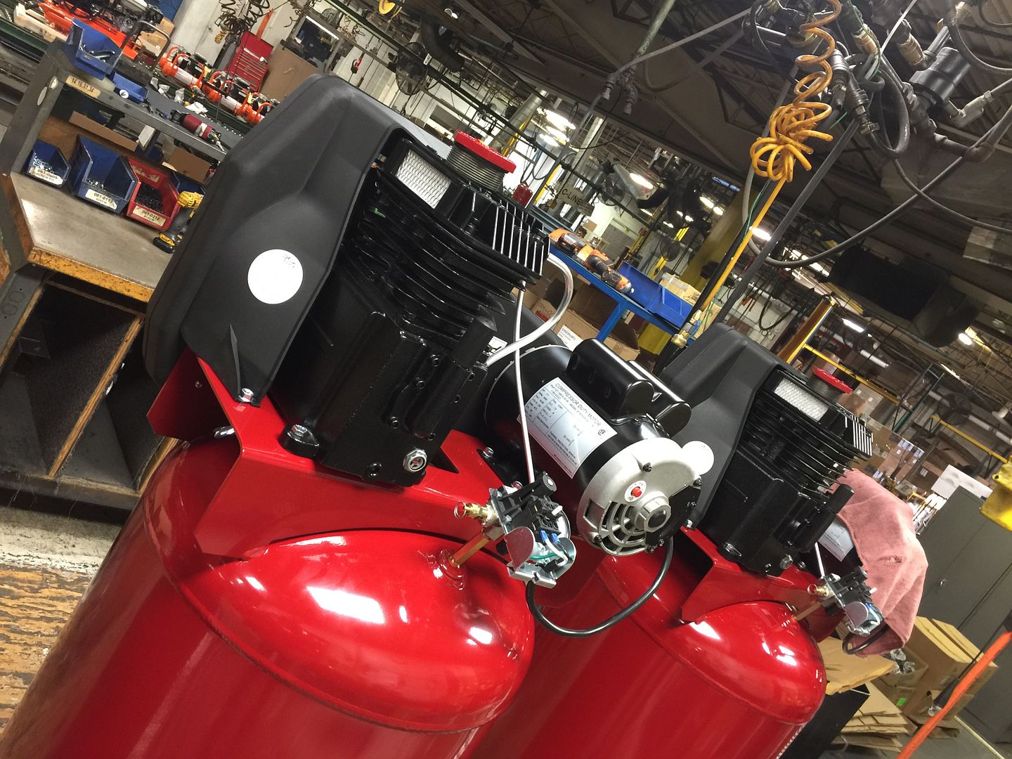
Made in America.
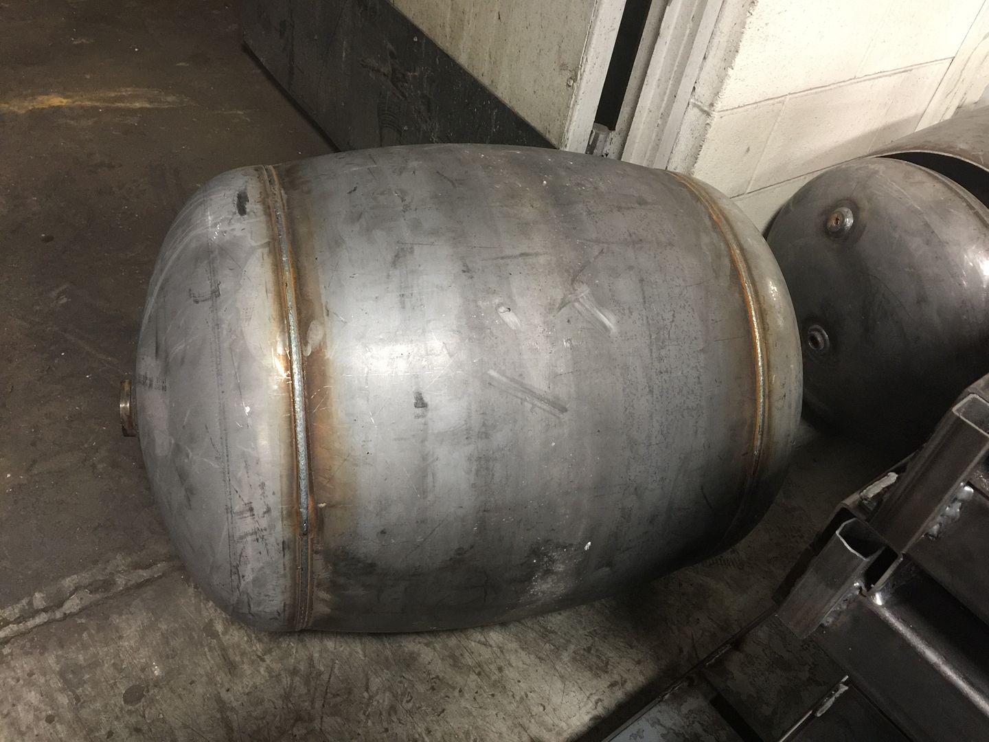
Last week I was back in the shop and they were testing out a new circ seam welder. The first new welder they have installed in many years, like decades. The new welder uses a twin welding process and is about 3 times faster than the current machine. Part of that testing is to qualify the welds it makes, since it is a new welding process. Most of the time a shop will just cut out sections of welds for bend and tension tests, but the shop decided to also do burst testing of the tanks, which I didn't get to witness, but did see the results.
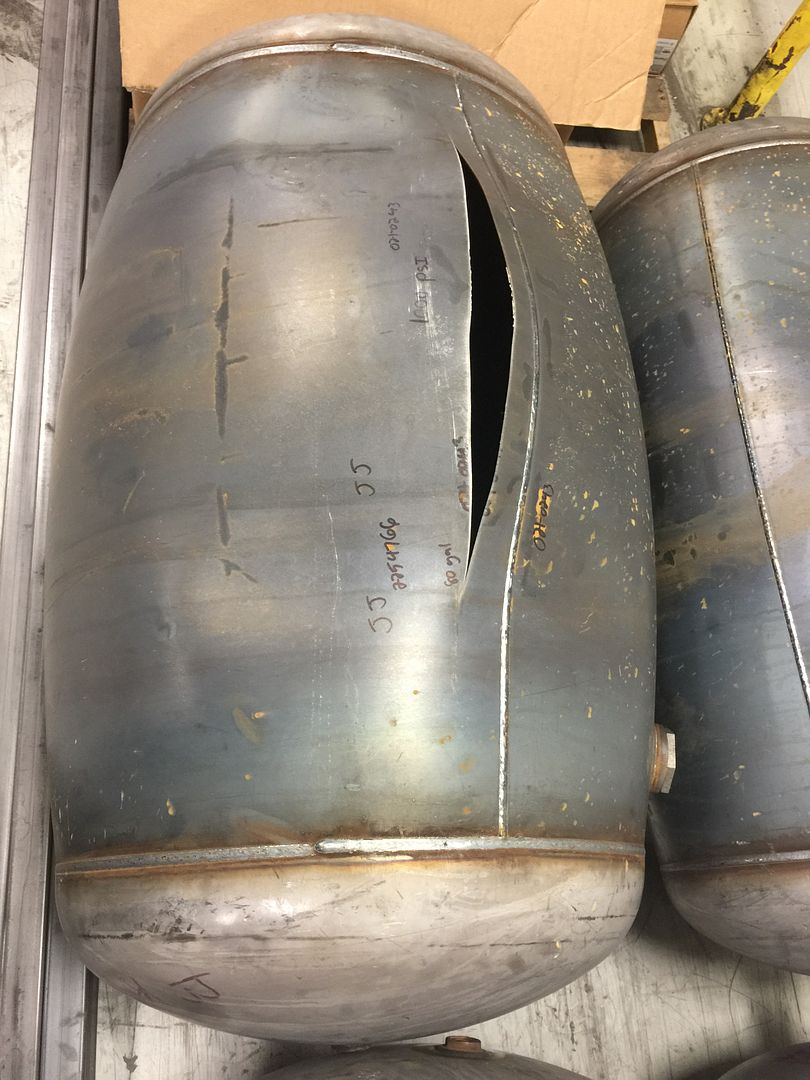
These are the tanks after being pressurized to the point of rupture. They use water, not air to do this, so when the tank let's go the energy is lost very quickly and not as violently as an air pressure test. Even so, when you see these pics you can get an idea of how strong these things are. All of them I saw held up to over 1000 psi.
The normal safety factor back in the early 2000's and before was 4 to 1. Later, the code shifted to a 2.5 to 1 safety factor which is in line with most of the foreign codes. It was also reduced with requiring more testing and better controls. The reason these went to such a high pressure though is partially due to having a minimum thickness that is higher than the calculated requirements. The ASME code has a minimum spec for certain things like boilers and air tanks where they could actually be calculated to hold a higher pressure than their ratings. This is only true for the lower pressure objects. Once you get over a certain pressure (depending on the diameter and grade of steel) that calculated minimum thickness is over the minimum required by rule.
Basically, the tanks have a tiny bit extra thickness. There are other factors used in other pressure vessels such as corrosion allowances, mill tolerances, etc. that make a difference but in this case it simply means the tanks are built a little stronger than they need to be.
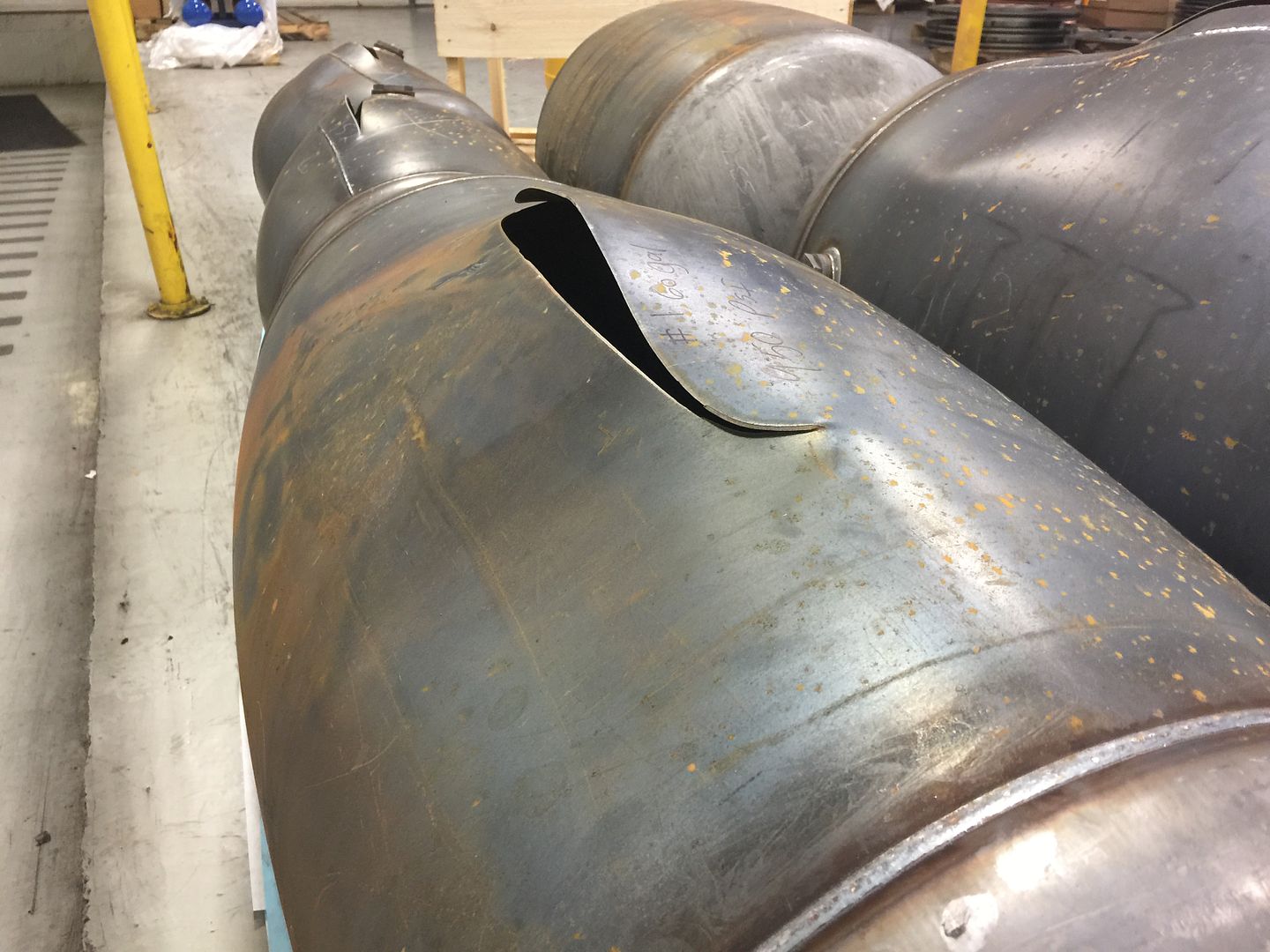
Look how they balooned out before letting go...
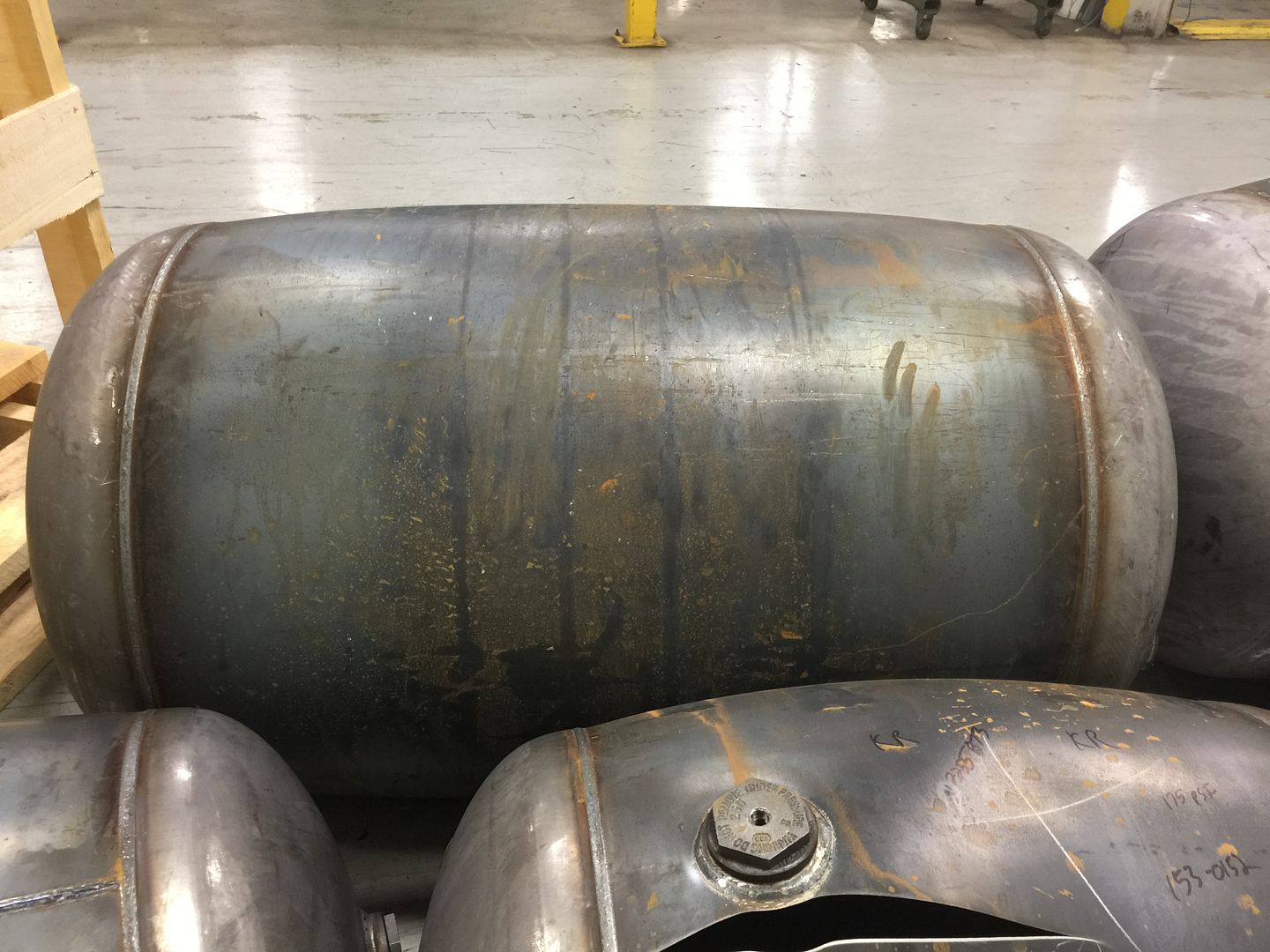
This one split outside the heat affected zone of the weld, so it's a good weld.
Same here...
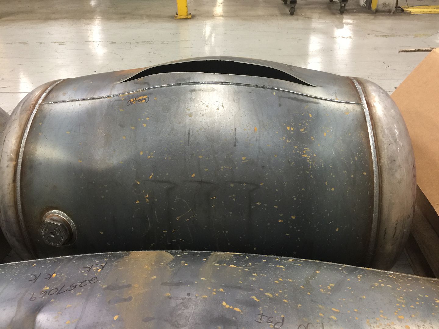
And here...
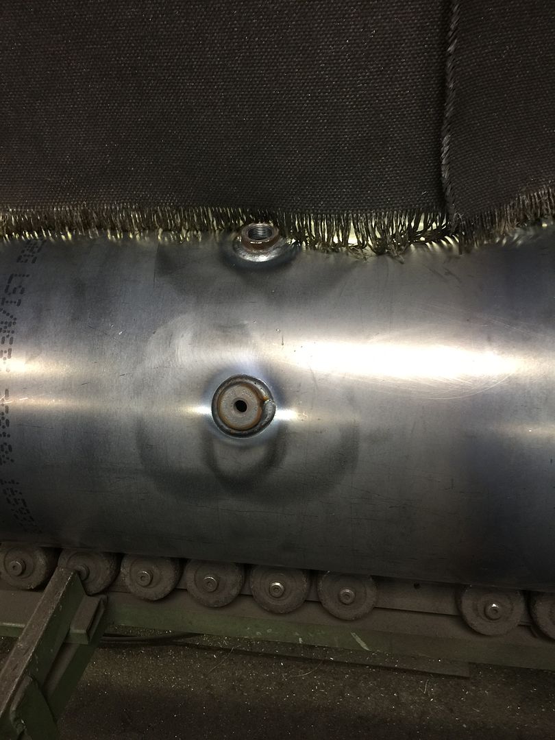
Right near the nozzle weld, which is expected.
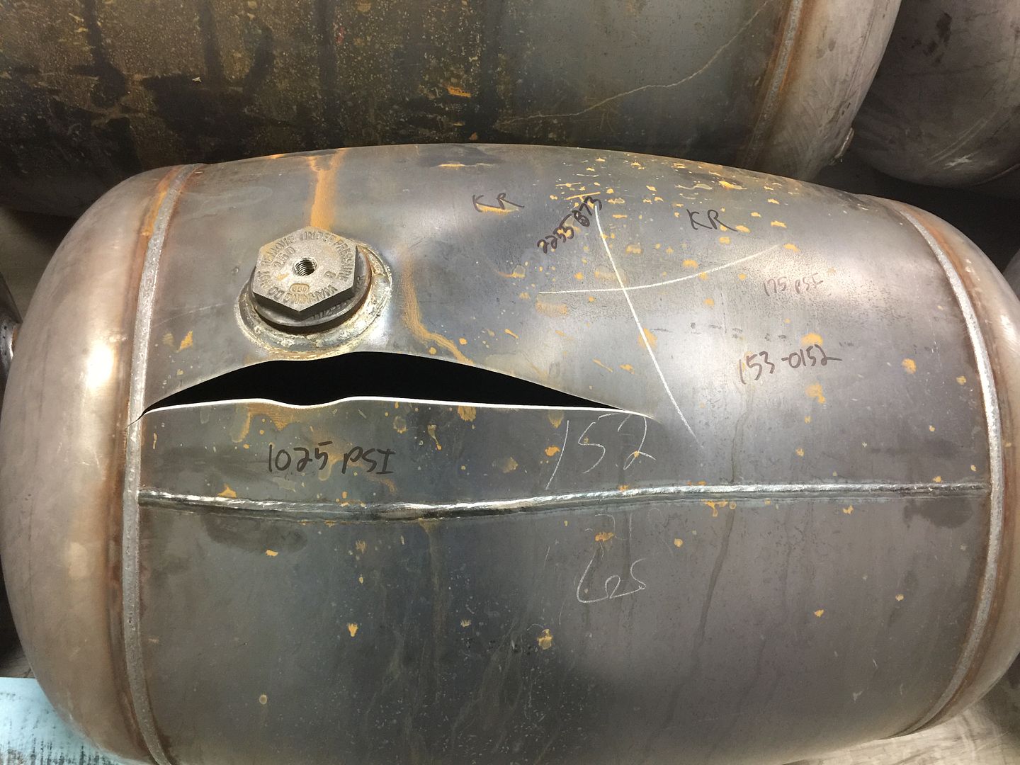
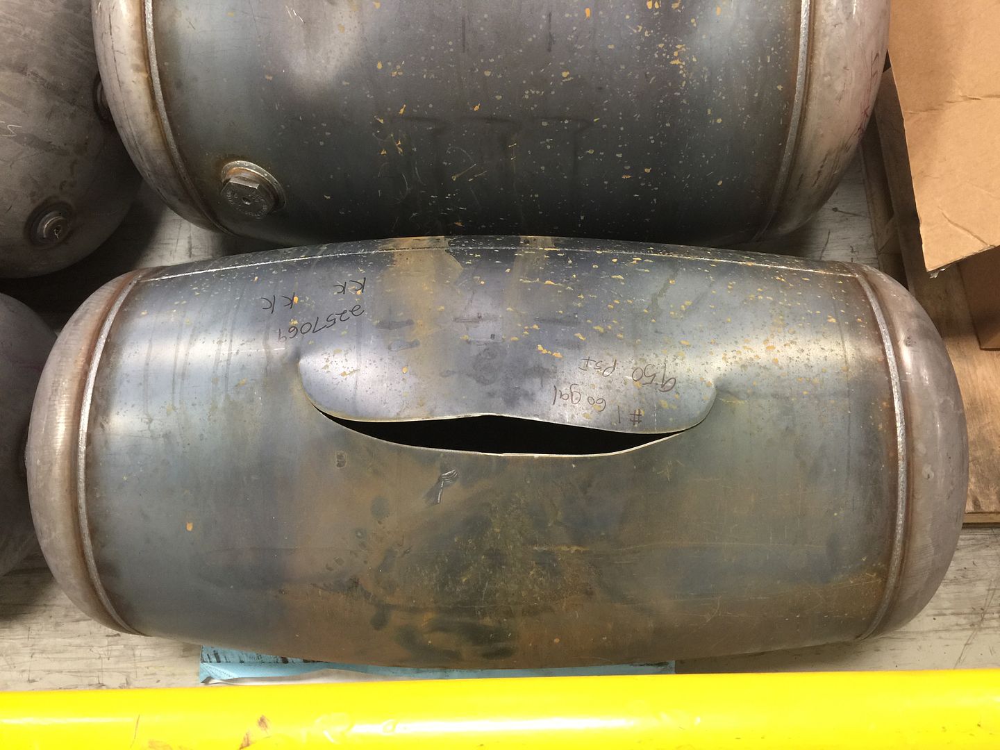
Looks like this one tore in the shell which then ripped the circ seam apart.
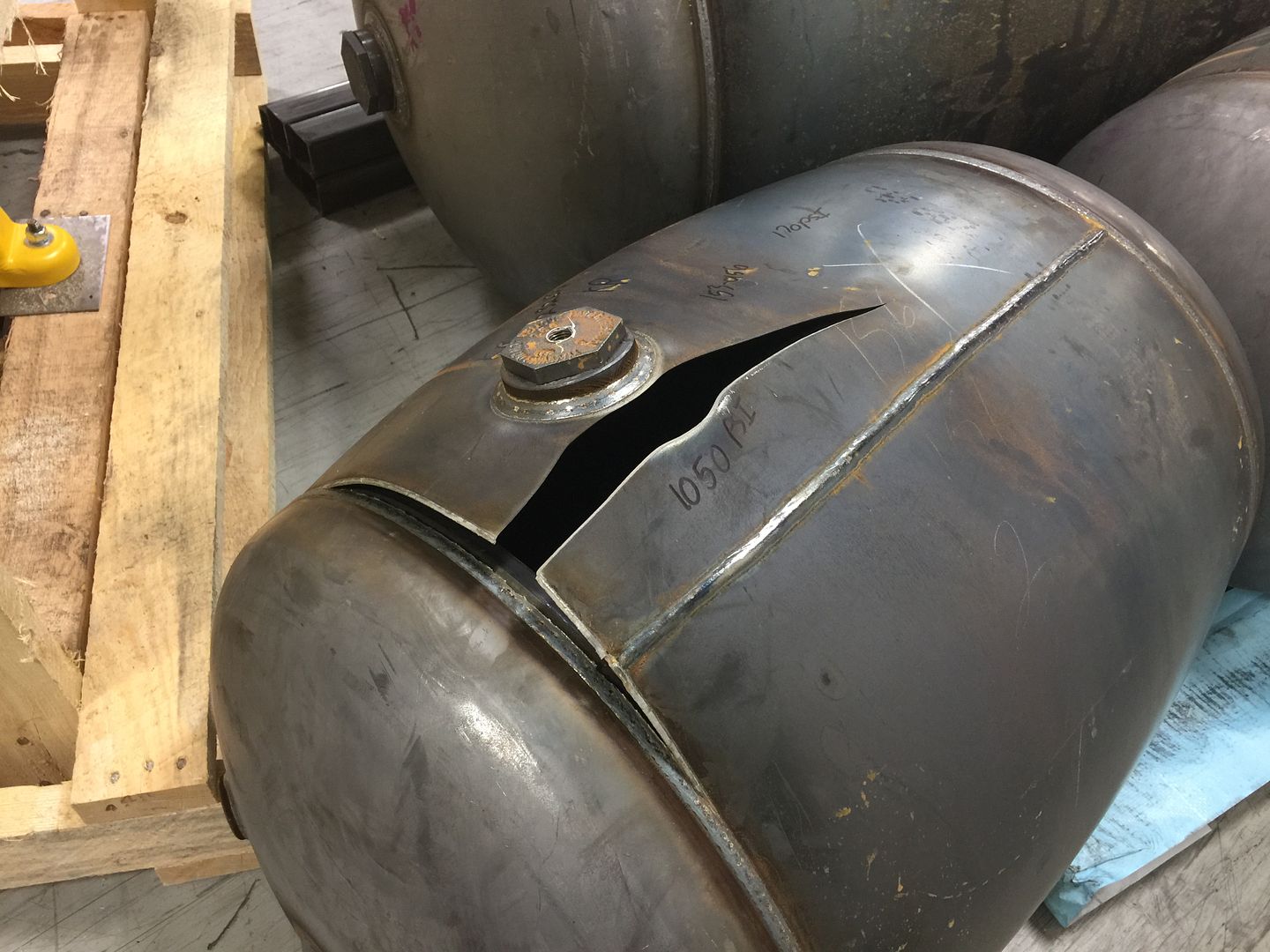
These next ones surprised me. The cast fitting failed before the tank let go.


This last one failed in the circ seam, which doesn't necessarily mean it failed the test. It depends at what pressure it blew, but they are still dialing in the welding process for this size tank.

There, you learned your something new for the day.
