The pink wire is the power feed for the gauge cluster. It is on pin 3 as you stated. It originates at the key on side of the fuse panel and runs to pin 3 on the gauge cluster.
Pin 4 is the ground to the sender via the fuse panel. Your gauge reads at 4 o'clock because it is not getting grounded through the sending unit.
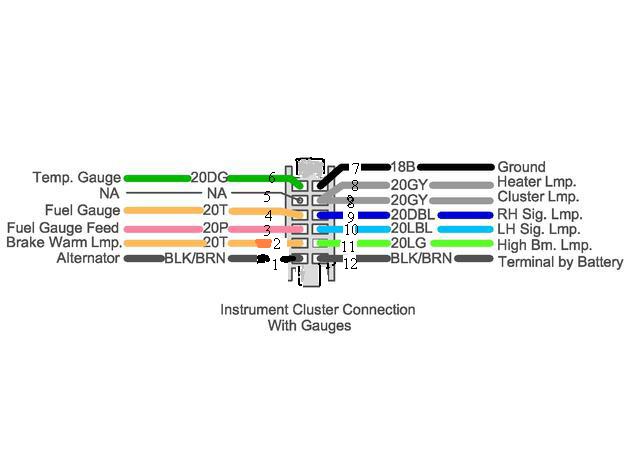
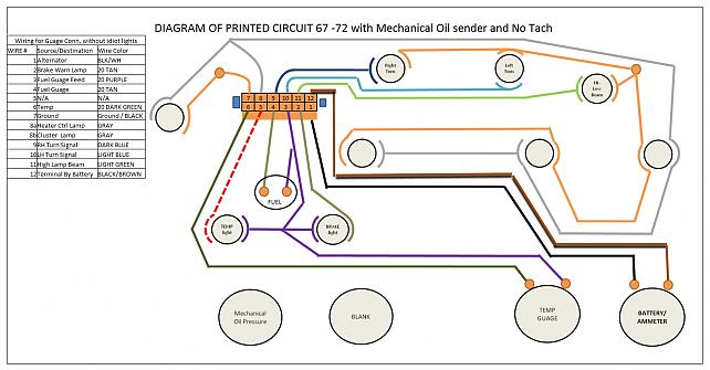
The gauge cluster circuit is shown here. Notice the pink wire feeds the fuel and the temperature gauges, the brake warning light and the temperature warning light for the light clusters. It is shown as a purple wire in the diagram.
Pin four is the tan or light brown wire that feeds the sending unit side of the fuel gauge and it runs to the fuse panel and thence to the fuel sending unit.
Since you have two tanks, I believe that the tan wire runs to the selector switch and then splits to go to each of the two tanks.
Do you have an electronic switching valve for the tanks or a manual lever switching valve?
If it's electric then you should have a power wire going to the tank selector switch along with the tan sending unit wire. Which ever it is you should never send 12 volts into the tank sending unit as it is a resistor that can get very hot without going through the gauge resistor and the tank resistor. There have been some instances of in tank explosions attributed to this mistake.
You should read 12 volts on the pink wire at pin 3 and you will read 12 volts on the tan wire because it is connected tho the pink wire through the gauge resistor. Once it goes through the load resistance and back to the grounded flange on the sending unit it will read less than 12 volts at that point, as ling as it is grounded back to the battery negative through the frame
This is the only fuel tank switching diagram I have but it may help you sort out the wiring. I think it's for the electric switching valves. It is for an 83 year so that's why I asked you if yours was manual or electric.
