Quote:
Originally Posted by Dukagora

I guess I now have another question! Initially I wasnt going to ask but its started eating at me as it doesnt make sense.
I was under the assumption that on a fuel sending unit with 3 ports the hoses were as follows and performed the following roles:
3/8 = Fuel TO the carb/engine.
5/16 = RETURNING raw fuel that was NOT used by the engine.
1/4 = Fuel....vent? Vapor?
When I did my initial testing to make sure everything worked, I never hooked up the ¼ line because I thought vapors would be the only thing coming out of those ¼ hoses. Not fuel. So both drivers and passenger were not hooked up. When I replaced all the hose, I did it one size at a time where there was hose, so I wouldnt, in theory, goof things up. Either way, after I got to this point I started the truck. Checked for leaks. Found a pool of it under the truck and figured I forgot to tighten a hose clamp. However it was coming out of the ¼ line. Dripping after I shut the truck off for a lot longer than I would have expected it to. No fuel from anywhere else. Passenger side only. The same line I thought was for fuel vapor and NOT fuel. This doesnt make sense though because why would you route fuel vapor to a tank selector valve if that isnt what the 5/16 does?
What this, to me, translates to currently is that the only return line for fuel is that ¼ inch? So that means as Im driving on the drivers tank, all fuel that gets returned is actually going to the passengers tank. And if the passenger tank is full
.eventually it will overfill and find a way out of the tank? Either way something must not be hooked up correctly.
Or am I wrong on which port fills each role? Maybe when the tank was bypassed years ago this is how it was done? For one tank it probably wouldnt matter? I saw a picture somewhere while researching this, and finding the info for me at least wasnt easy, but the picture showed only the 5/16 port labeled and said it went to the canister. Then I found another thread that lists it the way I have. This list makes sense with the fuel tank selector valve, or my understanding of it. This all lines up with hatzies Dual Tanks Theory of Operation thread. So maybe there was an issue and what I am seeing is the PO bypassing an existing issue to get fuel to return to the tank?
I assumed fuel doesnt go into a plastic canister filter and then back out but I might be wrong?
Someone show me the light please!!
I am certainly getting under the truck yet again tonight but wanted to make 100% sure I am correct on what I think I know before I tinker with it.
As always thanks for the help!
Edit: guess I am an idiot because it cant be plumbed any other way than 1/4" off the mechanical. So I wont be messing with anything. Still don't quite understand how 5/16" is the return line when it runs from the passenger tank to the canister though.
|
You really want to get this correctly plumbed. Fire is an unpleasant way to loose your toy.
Filling the LH tank with the return from the RH tank is extremely bad.
Likewise routing the return to the vapor can is extremely bad too.
The return and supply from the LH tank will go on the LH barbs of the valve and the RH set on the RH barbs.
The engine hoses are all by their lonesome on the other side of the valve.
Look at the cutaway pic in the theory of operation and open the Installation PDF from Pollack that I linked in that post.
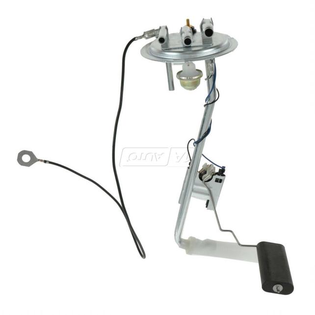
The senders have three connections.
- Supply: Identifiable by a long hardline in the tank with a mesh sock at the bottom near the float. Likely the 3/8" line. Use SAE J30R9 hose and spring band clamps... small diameter Ideal worm clamps are evil.
- Return: Short section of straight steel line reaching about 1/4-1/2 of the way down the supply leg. Likely the 1/4" line. Use SAE J30R9 hose and spring band clamps.
- Vapor: Terminates in a liquid separating unit immediately under the sender top. Usually 5/16". Tee this and run both to the charcoal can vapor connection. Use SAE J30R7 hose and spring band clamps.
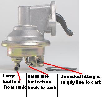
The mechanical fuel pump has three connections.
- Large barbed is the Supply line.
- Small barbed is the return line.
- Threaded inverted 45°flare is the carb feed.
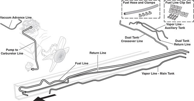
Here's a fuel line layout from LMC Truck...