You can check the turn signal switch easily if you have a volt/ohm meter.
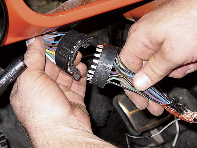
disconnect the steering column harness connector and on the cab side of the half moon connector, locate the purple wire. It should be the center wire in the connector. This is the wire from the fuse panel that supplies power to the turn signal switch and to the four turn lights on the vehicle. Notice the colors in the column connector half on the right do not match but they are in the correct order to match the left side.
Set the meter on the DC volts scale and connect the red lead to the purple wire and the black lead to a good ground in the cab.
Turn on the key and look for 12 volts on the meter. You must get that or the turn lights will not work. If you don't get anything then the flasher may be bad and need replaced.
Do the same thing on the brown wire without the key on. It is hot from the battery and doesn't need key on power.
Do the same thing with the white wire from the brake switch and step on the pedal watching for 12 volts on the meter as you step on the brake pedal. It is also hot any time the pedal is depressed.\
Now you're ready to check the switch itself.
1.Put the meter on the ohms scale.
2. connect the red led to the purple wire on the column connector.
3. Put the turn signal switch lever in the left turn position, and with the
black lead touching the following wires.
4. Check the yellow and the light blue wires for zero ohms.
5. With the lever in neutral you should see infinity on the meter.
6. Put the lever in the right turn position and check for zero ohms on the
dark green and the dark blue wires. These are the wires to the right turn
lights.
7. Put the red meter lead on the brown wire in the column connector and
with the hazard switch off, turn lever centered, check the same wires for
infinity.
8 Push the hazard switch to on and check The same four wires for
continuity with the brown wire, and with each other. Turn the hazard
switch off and there should be no continuity on any of the wires.
To check the brake lights if they aren't working.
1. Place the red lead on the white wire in the column connector and with
the black lead, check for zero ohms on the yellow and the dark green
wires, with the TS lever in the center.
2. Place the lever in the left turn position and check for zero ohms on the
dark green wire and infinity on the yellow wire.
3. Place the lever in the right turn position and check for zero ohms on
the Yellow wire and infinity on the dark green wire.
To check the horn wire, the black one.
1. Place the red lead on the black wire in the connector and the black lead
on the column housing mount or any unpainted part of it.
2. Press the horn button and check for zero ohms on the meter, then let it
off and check for infinity.
I hope I got this all right. I'm doing it from memory.