VetteVet, in your earlier post you are showing the 10 DN (Ext Reg) alternator with the resistor going to the Acc post, but on the 10SI (In Reg) you are not. I think that may add to the confusion. You did say, "
the diagram with the idiot light and the Accessory wire feed to the fuse panel is left out but it still is in the circuit". I assume this qualifying statement is to let people know that the original resistor is still in the circuit, but by omission it makes it vague and confusing.
I had a problem of not knowing what I was dealing with because Petey did not say what type of alternator he was using and what electrical draw he had so I was trying to cover all the bases.Once I got the details it narrowed down the problem considerably.
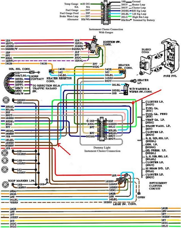
I was afraid that this might be confusing because it does not show the parallel resistor. That's why I added the text. The second diagram I posted shows the routing to the firewall block but does not show the brown wire going all the way back to the gauge cluster plug. I was hoping I wouldn't have to write a term paper to illustrate the circuit. The red arrows show the brown wire to the idiot light that parallels the resistor wire, Brown/White. The feed wire for the idiot light comes from the Key switch to the dash cluster via the fuse panel, to complete the parallel circuit back to the firewall plug, and from there it is one brown wire to terminal 4 on the external voltage regulator OR to terminal 1 on the I/R alternator.
I like this drawing a little better because it helps to shows that
nothing under the dash needs to be changed when converting from the DN to the SI alternators.
Fixit-p, I changed your drawing a little. Voltage on terminal #1, is connected to one side of the field, but it also biases TR1, turning it ON. In order for current to flow through the field, it needs a ground and it is supplied through TR1.
I think we're going to be in some disagreement over the roll of the resistor that is in parallel with the indicator lamp.
That resistor has one primary function. If the lamp fails, the regulator and generator will continue to function normally. If you didn't have the resistor and the lamp went bad, you would have an open circuit. The resistor completes the circuit if the lamp is bad. The resistor allows a different voltage on each side of the lamp so that the lamp will glow when there is a generator failure.
In this we disagree. The resistor does provide an alternate path for field excitation, however it also protects the transistors in the internal voltage regulator, and it also prevents feedback from the diode trio to the ignition circuit, which would allow the engine to continue to run with the key off.
The resistor has nothing to do with the light function as it is controlled by the voltage potential of the battery and the voltage output of the alternator. The resistance of the light itself determines the intensity of the light in concert with the voltages of the battery and the alternator.
I don't know if the "
resistor limits current flow to from the alt protecting the regulator or diode trio" as fixit-p said. It INCREASES current flow to the regulator.
I don't thin so.
You know,,, two resistors in parallel (resistor and lamp) have less resistance than either, alone.
If you use the lamp and no resistor the Alt will not begin to charge, but the lamp will glow. The voltage at terminal #1 will be too low for the field and TR1 will not be turned ON. The Alt has some residual magnetism. so you must rev the motor high enough so that the diode trio can provide the current necessary for the Alt to begin to charge.
Again I disagree, what you describe is a one-wire where-in the field is excited by the residual magnetism
in the field and aided by leak over current from the one-wire regulator. With the light you get instant voltage and current to the alternator field and full voltage at idle.
If you are wiring from scratch or don't have an Acc, ignition post such as an older truck with DC generator you can wire a resistor directly across the lamp.