Quote:
Originally Posted by SeanB242

Yes GR8-68 it is very helpful. So i guess Ill go ahead and ask another question. HAHA. In the early 90's I had a 68 shortbed. I hate the way a factory runs wires and has been a pet peeve of mine. I had converted that truck to internal regulated alt. Fast forward to 95 and the truck was replaced by a 66 Chevelle which I still own, whats left of it but that is another post. I had also tidied up the wiring and and changed to internal regulator. So its been a while since I did this. On this truck I once again removed the regulator and im not sure I rewired it correctly. The red wire out of the plug on the alt. is ran to the red lug on back of alt. Not sure what wire to run the second wire in the alt. plug from? or to, not sure which? haha
|
Allow me to butt in.
The answer to these questions is easy since I have advised hundreds of guys on how to do it. It doesn't matter what vehicle you convert to internal regulated, all you need to do is to feed the alternator plug with a resistance wire to the no. 1 terminal from a key on source, and feed the no. 2 terminal from a junction of all the wires that power the accessories in the vehicle.
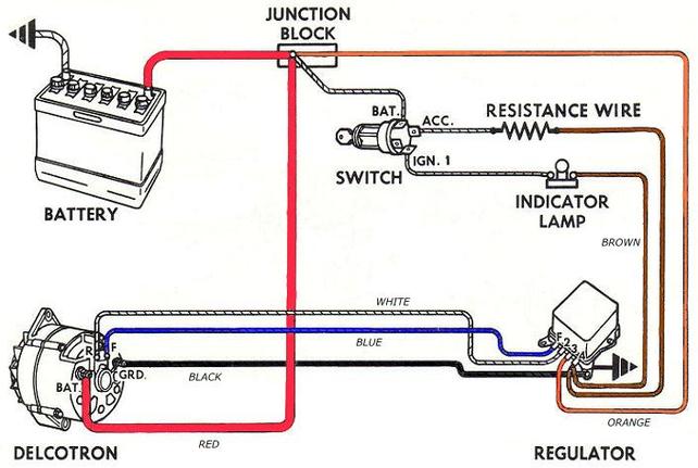
The no. 1 wire is the wire usually run from the key switch and has a built in resistance equivalent to 10 ohms. It is present in most all of the wiring circuits that use alternators, whether they are internally or externally voltage regulated. This is the exciter wire that turns the alternator on. Normally the job of exciting the alternator is handled by the charging light, with the resistance wire as a back up in case the light bulb blows. These two sources of power are run in parallel but the gauge dash does not have the light as the resistance and instead uses the resistance wire and the battery gauge to indicate charging.
This diagram illustrates the above.
Quote:
Originally Posted by SeanB242
My dash has the gauges in it. According to the wiring diagram the brown & white wire from the ignition switch goes to the bulkhead and is just brown out the the regulator. Since I replaced all my wiring I just need to extend that wire out to the plug at the alt? Also the diagram shows a black & white wire from the instrument cluster also going to the alt. Do I run that wire out there also?
|
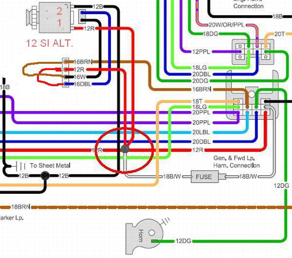
You are correct about extending the brown/white wire to the alternator plug, no.1 to be exact. since you eliminate the EVR, you will extend the brown wire all the way to the alternator. Some guys just jumper the brown wire at the EVR to the white wire that goes to the R on the 10DN alternator OEM alternator, and jump the red sensing wire on the EVR plug to the blue wire which goes to the F terminal on the OEM alternator, Then they connect the white wire to the no.1 terminal. (extended the brown wire) and connect the blue wire to the no. 2 voltage sensing terminal. (Extending the red wire) on the internally regulated alternator. Of course they have to change the alternator plug to make the connections.
To illustrate this.
This works OK but I like the simplified version shown below which illustrates exactly what you said about extending the brown wire to the IR alternator.
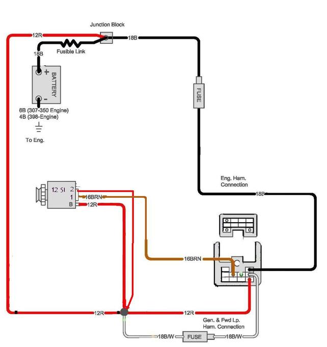
Now I'm not a big fan of looping the no. 2 terminal, sensing wire, on the IR alternator over to the output lug, due to hindering it's ability to compensate for voltage drops down stream from the alternator. It'll work but it will sense the voltage at the alternator output, and not at the point where all the loads draw juice from. It's possible to get a 2 volt drop on the wires going to the headlights wipers heater etc. If you notice in my last diagram I run the red sensing wire to the junction of all the power wires wherever that junction may be.
This is a great explanation by Mad Electric on this feature. Be sure to read the other articles shown in the website for some very informative information.
http://www.madelectrical.com/electrical-tech.shtml
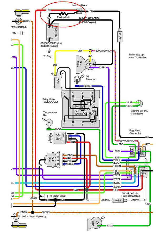
Your last question on the black/white stripe wire. It is probably the alternator side of the battery gauge, and should be connected with the alternator output wire wherever it supplies the power to the main junction.On your Chevelle it should be connected at the horn relay.
There should also be a solid black wire somewhere near the battery positive terminal to read the battery state of charge, and relay it to the battery gauge. This one is normally connected to the junction bolt on the right fender of the 67 to 72 trucks.
Here is a diagram of the ammeter wires on the trucks, notice the 18 gauge wire in the circle on the top, and the other one with the stripe at the bottom junction of the power wires. They would all be mounted on the horn relay on your chevelle.