Quote:
Originally Posted by Big Block 454

Thx Vet,
I just got the truck and am trying to sort out a number of things including the charging issue.
Went to the muffler shop yesterday and had to jump it to get home. Got home and pulled the battery cable and it quit running. Since it won't run without a battery and the fact it stranded me it's obviously not charging.
Had the alternator tested and it's good - they had to utilize the R and F terminals to test it so it's not a 1 wire.
The hot wire on the back of the alt. is run direct to the battery but there's nothing plugged into the top which is marked R and F.
I suppose the easy way out would be to get a 1 wire but I'd like to keep my chrome alt.
I have a couple more questions:
1. The 71 models don't use a horn relay or does the painless kit eliminate it?
2. Being it's not a 1 wire it will never charge without R and F connected as it currently is?
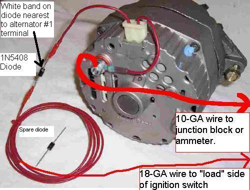
3. And since it seems to be internally regulated will this simple diagram work? (The color diagram showing the alternator and a diode).
http://www.ytmag.com/cgi-bin/viewit....rtips&th=24290 |
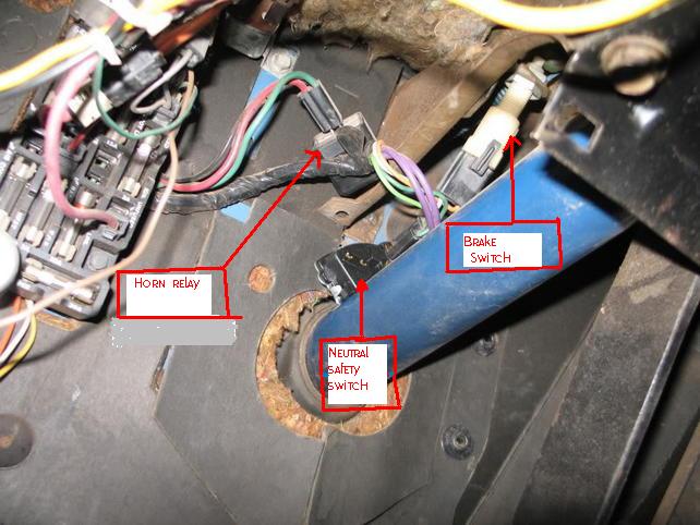
1. Look for the horn relay here. It might be over the fuse panel also. Look for a large red and green wire and a smaller black wire in a terminal end that plugs into the relay.
2. R and F are the terminals used on alternators with the external voltage regulators. The internal alternators use 1 and 2 for the sensing and field terminals. I have seen some external reg alternators with the terminals on the side or top but usually they are on the back. I saw a 71 the other day just like that. How did they hook up the alternator when they tested it? Did they use a regulator or a feed wire to the F terminal? If they used a regulator then you will have to go to that or change the regulator inside the case to an internal one.
3. If it is internally regulated then the picture in the thread you linked will work but You should not need either the diode or a resistor since you will have a charge light or a brown resistance wire from the key switch ( if you have an ammeter) Then you just need to connect the brown wire on the engine side of the firewall to the F terminal and the red wire to the R terminal.
I'll double check that and edit if it is backwards. The normal internal regulated wires would be brown to no.1 and the red to no. 2. Notice that is how this one is wired.