FrenchBlue72
Please Refer to figure below
Background Information
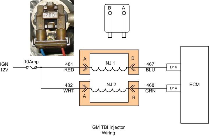
Basically, GM implemented a very simple TBI injector circuit. In this implementation ECM acts as a switch pulling Pin B of injector connector to ground completing the circuit energizing injector - fuel is delivered. Ignition switch supply is provided via two circuits 481, 482 (red and white wires) and are always on (as long as ignition key is in run or starting position).
Checks
Requires a functioning DVM - no excuses now, alright???
Injector coil
1) Everything is off, disconnect injector connectors from injectors by gently squeezing release tabs. Set DVM to measure resistance (Ohms), set to lowest range available <300 Ohms. Ignore this if you have a fancy auto ranging DVM. Measure resistance of each injector. Depending on your DVM and test lead resistance you should be able to measure individual coil resistance - about 1.1 to 1.5 Ohms for typical GM injector. If you are reading very high resistance - time to cry. If injectors check out then step 2.
2) Verify ignition voltage supply
With both connectors disconnected make sure that they do not come into contact with anything in the engine compartment. Once secured, turn ignition into run position and measure voltage at Pin A off each connector. With a good battery you should see 11.5 to 12.0Vdc with respect to ground (bat negative terminal). If there is no voltage verify ignition fuse.
3) Re-install injector connectors if step 2 is good.
With ignition on, engine stopped both Pin A & B should measure 11.5 to 12.0 with respect to ground. If Pin B fails to measure same voltage as Pin A then it is possible that connector is making a good contact with injector pins or there is an open injector winding when connector is installed on injector.
4) ECM PWM verification (this requires NOID or un-powered 12 volt test light)
For this test DVM a typical DVM response time is to slow (there are units that can measure frequency or pulses specifically for PWM circuit troubleshooting) and a simple un-powered 12 volt test light will do the trick.
Connect ground lead to engine ground and probe Pins A & B of each injector connector - light should be one for both as long as ignition is on, engine stopped. Get a helper to crank engine while probing Pin B of each connector - the light should be blinking off periodically. This is normal. Otherwise, if it remains solid that may indicate that ECM is not pulling injector circuit 467, 468 to ground. This may be caused by brake in harness, bad injector pull down circuit, etc. Manual shorting of injector control circuit - Pin B is not recommended, but this can only be done once supply voltage pind has been verified (red/white) and only for a short time.
//RF