The conversion is fairly simple especially if you have a stock harness.
The difference between the gauge dash and the idiot light dash is, where you run the large output wire from the alternator. If you run it anywhere but to the stock location then the battery gauge might not work.
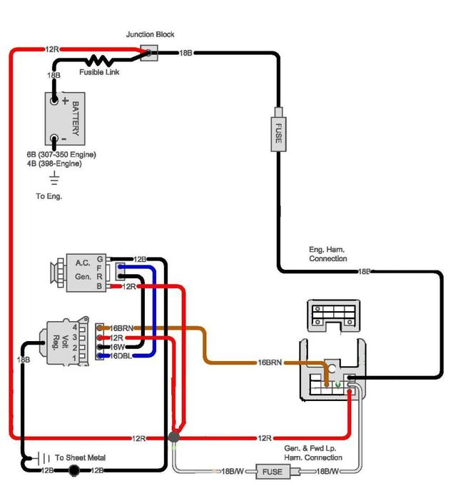
Here is the stock wiring.
here is a simple jumpered conversion.
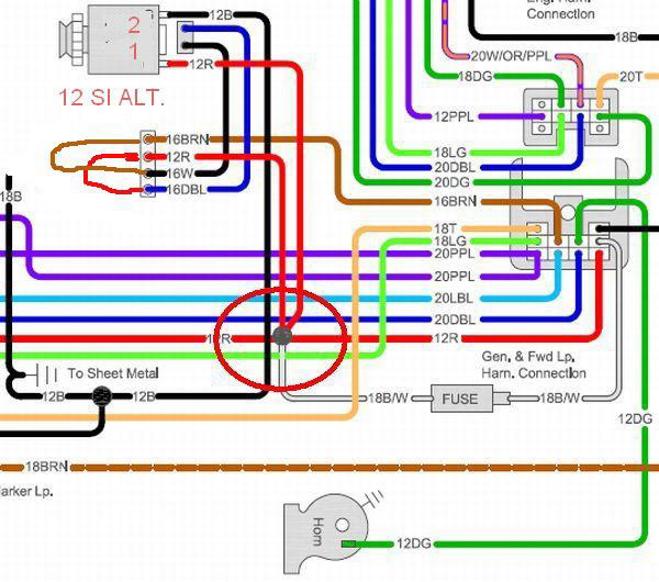
Notice all you do is pull the plug off the external regulator and jump between the no. 2 and your exciter wire which is white.
Then jumper between the no. 1 and the wire which is hot all the time on your regulator. In the stock harness it's a jumper between the brown and white wires and the red and blue wires.
I think I have it figured out on your solid state regulator. The white wire serves as the brown exciter wire with the jumper to the no, 4 position where the brown wire normally goes and it also takes the place of the no.3 wire which is normally hot all the time, because when you turn the key on it also becomes hot.
Then 1 and 2 go to the alternator where 2 connects to the R terminal on the alternator and 1 connects to the F on the alternator. I believe you had those two reversed at the alternator, didn't you say that.
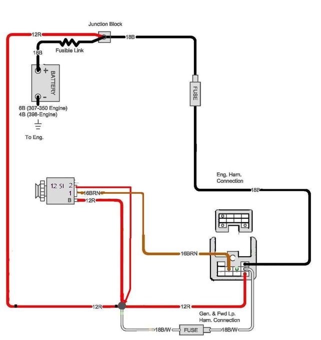
When you do your conversion you only need to run the white wire on your setup (which should be brown) to the no. 1 on the SI alternator and then you have a choice to loop the no. 2 wire on the alternator to the large post on the back of the alternator Like Todd does or you have to run a separate wire from a junction of the battery and alternator feeds like the diagram shows.
I prefer to do that because it gives the regulator in the alternator, a better sense of what the voltage is in the circuit nearer to the draws on the battery, and will allow it to step up the output voltage to compensate for those draws.
Setting it up like Todd does will work but it only tells the regulator what the voltage is at the back of the alternator and you could actually get dim lights and low power in the cab.
In a nut shell all you have to do to get the internally regulated alternator to work, is to wire the exciter wire from inside the cab to the no1 terminal on the
SI alternator and run a 12 volt source that is hot all the time to the no. 2 terminal on the SI alternator .
This is how I do it and it is clean and neat and gets rid of the external regulator altogether. It shows the exciter wire coming from the firewall connector as a brown wire which it is in the stock harness. Check the first diagram above.
Then I just run the Red wire (hot all the time) from the junction Which is circled in red in the first diagram to the alternator voltage sensing terminal no. 2.
You can buy the SI alternator plug in any of the autoparts stores for about $5 or just get one at the local pick a part junkyard. Then you just splice the two wires in.