|
Re: Fuel gauge wiring and voltages
.................................................................................................... ...
Quote:
Originally Posted by cjensen_68

Vette, the switch is an electrical switch. it's set up correctly. I pulled the dash and opened the wiring. It's a bit of a mess. There is no ignition switch. It's basically a toggle switch with a push button to start the engine but there is a lot coming off of that toggle switch and I don't like it. I have already bought the switch and parts and will be going back to what factory came with. The main hot wire feeding the toggle switch was melted when I opened the harness up.
This is a common problem with our trucks after 50 years of current going through the plastic connector and the red wire which is the main current supply for all the key on items it supplies.
Here is the new switch and the wiring to it. Hopefully your color coded wires will match.
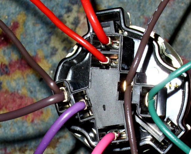
I was wrong with my initial thoughts on where the tan wire went. I thought it went to the brake switch but it went to the fuse panel. That's why I kept seeing 12V on pin 4 even with the connected off of the cluster. I got that situated now.
I do have another question with the fuel gauge though. Can my fuel gauge be working but have too low of resistance? I rigged it up to how it should be and it worked. I read another post where TBONE1964 did a write up on how to test the fuel system. In there his readings were different than mine on the fuel gauge. I had the dash out and between the feed and sending unit terminals I had 39ohms when tbone had 44 (not too worried with that one) but between the sending unit and ground he had 98 and I have 66. And for the feed to ground he had 140ohms and I had 75. Are those readings acceptable?
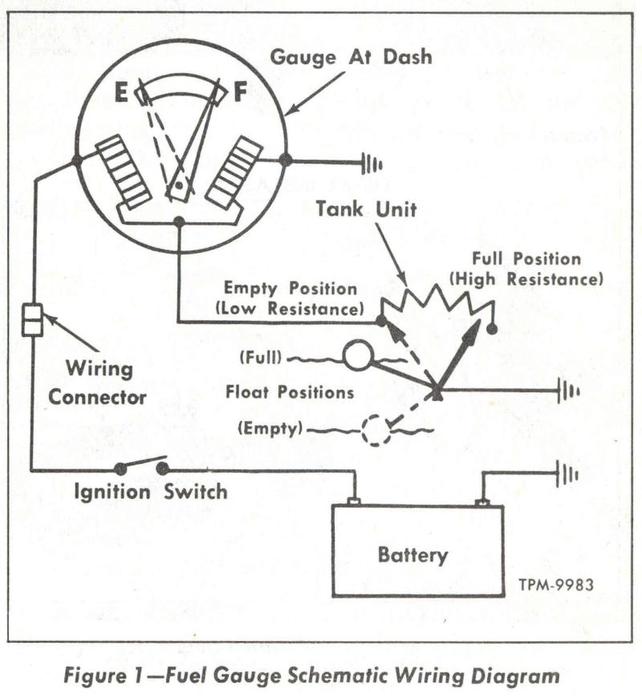
The readings do vary a lot, but those are ok. Just remember with the fuel gauge- high resistance mans more fuel reading and low resistance means less fuel reading on the gauge.
Here's a schematic on the circuit. It doesn't show the tank switch you have, just the regular trucks.
I did find a schematic that was color coded from this forum. I had printed it out at work on a 11x17 paper. What a life saver that is. |
The wiring diagrams that I have seen all show a wiring error on the wiper motor wiring which would produce a dead short to ground and blow the wiper fuse the second the wiper switch is selected.
Here it is with the corrected wiring below. Notice the yellow jumper for the washer is connected to the low speed terminal, which is a ground path for the motor.
__________________
VetteVet
metallic green 67 stepside
74 corvette convertible
1965 Harley sportster
1995 Harley wide glide
Growing old is hell, but it beats the alternative.
|