Quote:
Originally Posted by 70zz4

My current set up is stock external regulator on 70C10 w/ gage dash.
I want to use serpentine alternator from 97 GM motor.
I read through the material and still very confused.
Was planning to use the adapter to go from SI to CS.
Confused about what output wire your post is describing for the gage dash to work.
Any further info very much appreciated.
|
Very simple, it's the wire off the back of the alternator that goes to the main junction in the truck harness where the wire from the battery and the wire to the cab and the wire to the voltage regulator are joined.,
You see, the battery gauge tells you whether the alternator is charging or the battery is discharging, by reading the voltage output of each one. It does this by connecting a charging wire between the two, called a SHUNT. Then a small wire from the battery and another one from the alternator connect to the end of the shunt wire, and they each go to a side of the battery gauge.
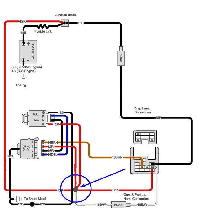
The circle with the blue arrow is the main junction and the small wire with the fuse is the alternator side of the battery gauge, up by the battery is the other wire on the junction block that is the battery side of the gauge. It also has the fuse in it to protect the battery gauge from over voltage. If either fuse is blown the gauge will not work.
If you notice, the large red wire from the back of the alternator is routed here and the wire on the left edge of the diagram connects the alternator output wire to the battery positive post via the fender junction and the fusible link from the battery post. that wire is the shunt. If you run the alternator wire straight to the battery or to the starter post, it won't be connected to the end of the shunt and the gauge wire won't be able to read the voltage output from the alternator.
Here is how I convert the OEM system or an SI charging system,to the newer CS alternator. You can see that the wiring is very similar. You just have to run the stock brown wire that went to the external voltage regulator, to the L terminal om the CS alternator, with a resistor soldered inline.
And the red wire from the external regulator plug which also goes to the main junction, to the S terminal on the CS alternator.
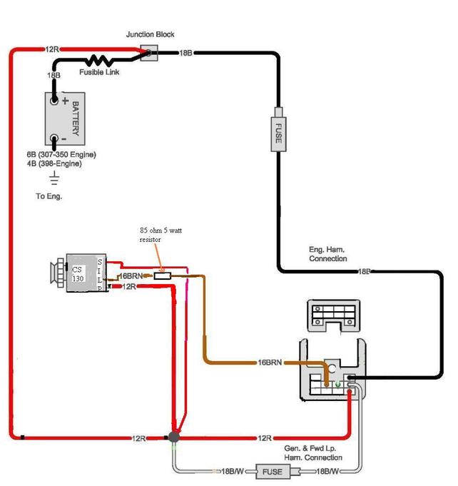
You don't need any adapters if you can find the CS harness with the plug for the alternator. The junkyards are full of them since they were used on about every GM car and truck made after 1986. Once you get the plug in for the alternator all you have to do is splice the brown wire into the the brown wire in the plug harness, don't forget to solder in the resistor, and splice the red wire into the S terminal wire. You won't need any of the SI stuff that is there.
If you can't find the brown wire for the L terminal that went to the original voltage regulator plug, it starts at the firewall block by the master cylinder.
I recommend that you upgrade the alternator output to an 8 gauge wire for the extra amps you may draw with the larger alternator. All the other red wires are 12 gauge from stock and they are large enough
Hope this helps.