To read the original thread and discussion on this topic go here- LINK
UNIVERSAL JOINT R&R (1 OF 6)
In my Project thread, I posted a blurb on the work I did on my driveshaft. A few people have asked me for more detail than I provided in that thread. In this thread, I explain my step-by-step approach for removing and installing a universal joint (UJ) in a yoke using common tools and a hydraulic press. I assume that the driveshaft has already been removed. The driveshaft will need to be securely supported but I do not discuss that here.
There are three basic parts to deal with when removing and installing a UJ.
1. Lock rings: retain the UJ assembly in the yoke.
2. Trunnion: The X-shaped piece that provides the main structure. The cylindrical machined surfaces of the trunnion act as in inner race for the needle bearings and the flat ends act as thrust bearing surfaces.
3. Bearings: Also called end caps or bearing caps. They are either pressed into a yoke and retained by lock rings or secured on a flange by U-bolts. They act as outer bearing races for the needle bearings and thrust bearing surfaces for the end faces of the trunnion.
In this narrative, opposite ends of an assembled UJ are pressed into a yoke and held in place by lock rings. To illustrate, I used a yoke assembly and UJ from a half shaft of a 60-something independent rear suspension Corvette that appeared not to have been touched since it left the factory.
First, clean off all the grease and dirt using whatever solvent or soap you prefer (the cleaner, the better).
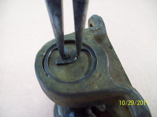
Next, remove the lock rings. A pair of needle nose pliers works OK but they may be difficult to keep a good grip on the lock ring.
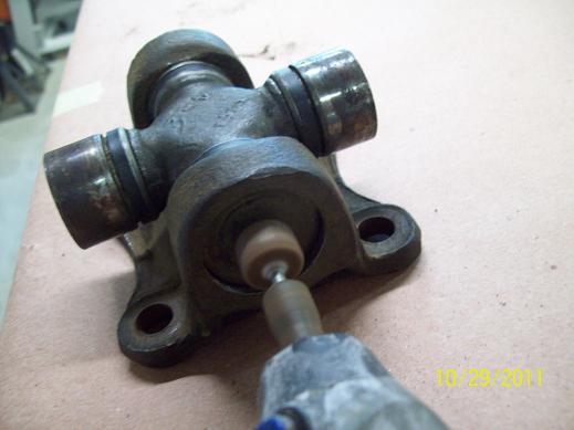
If there are any burrs or deformations on the perimeter of the yoke bore outside the bearings, now is a good time to remove them so they won’t interfere with the bearing as it is pressed out. An appropriate size grinding wheel installed on a Dremel tool works well.
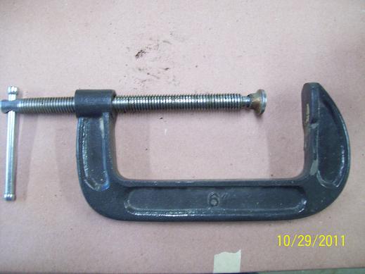
I first try to press out the bearings with a large C-clamp and a socket. For my truck, a 6" C-clamp is a good size to use.
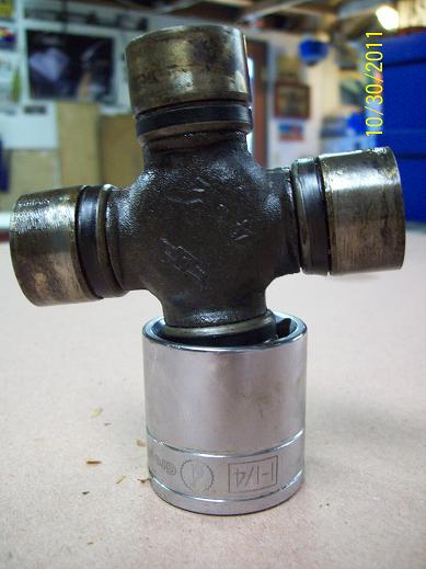
To determine the socket size to use you need to know what UJ you are dealing with. I have a C20 so I’m dealing with two sizes of UJ. The UJs at the transmission and carrier bearing are both Series 1310. The UJ at the differential is a larger Series 1350. The bearing OD of a Series 1310 is 1.062 inches so I use a 1 1/8" socket. The bearing OD of a Series 1350 is 1.188 inches so I use a 1 ¼" socket. In this narrative I am working with a Series 1350.
This site has some good basic UJ info.
http://www.driveshaftspecialist.com/...D%20Guide.html