We'll need to go back to basics here so that you understand how the battery gauge works, then it will be much easier to wire and understand.
The battery gauge reads the voltage differential between the battery and the alternator. When the alternator voltage is higher the gauge will read "charge"
and when the battery voltage is higher the gauge will read "discharge".
In other words it tells us when the alternator is charging and when it isn't.
In order to do this, there there has to be a connection between the alternator output and the battery positive terminal which each terminal of the battery gauge can be connected. Both terminals cannot be connected to the same place or the gauge won't be able to read voltage difference between the battery and alternator.
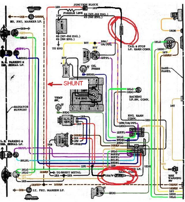
This connection between the battery and the alternator is called the "SHUNT"
and it is shown in the diagram below along with the circled 4 amp fuses in the 1 and 12 wires.
On the stock factory trucks these two wires are run to the firewall connection block and then to the gauge inside the cab.
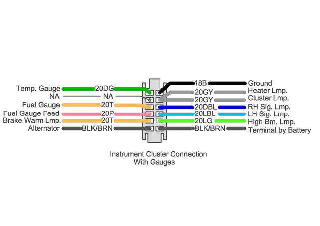
Here is the plug connection for the gauge dash and the wiring changes that need to be made on the plug.
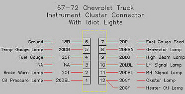
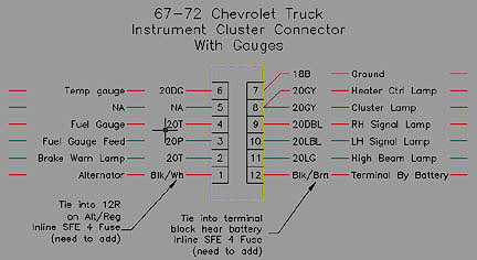
Here is the comparison between the idiot light cluster connections and the gauge cluster.
light cluster
gauge cluster
Besides taking the no.2 blue wire out for the oil light to mechanical oil pressure gauge, you'll have to pull the no.5 green wire for the temperature light and the no. 6 pin will be the temperature sender wire to the temperature gauge in the cluster. You'll also have to change the temperature gauge sender in the left cylinder head, to the correct one for the temperature gauge.
.................................................................................................
The alternator will say P L I S or S F L P and the L wire is the one for the resistor. Normally you won't need the I or P terminals or the F. Only the S and
the L terminals are used. Take a look at the alternator plug or the alternator body and check the terminals. You need to be sure of what type you have.
I run my conversion harness like this.
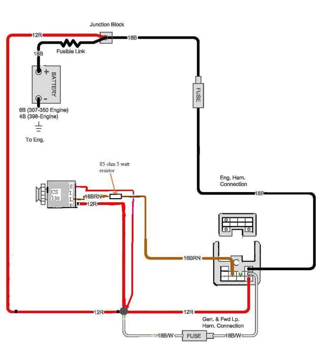
Notice the resistor in the L wire and the fuses in the 1 and 12 wires.
You'll probably need to upgrade the alternator output wire to an 8 gauge to handle any accessories like the cooling fan or a stereo amp etc.