Ever since my original gas pedal wore out and I switched to an aluminum racing pedal, Ive been struggling to obtain the smooth pedal operation I was after. Recently I noticed a few members had installed the 1971-72 C10 cable throttle in their 60-66 trucks. Further research showed this to be a very popular swap with the 67-70 crowd as well.
Other than 2 photographs another member posted, there wasnt much helpful information available. When I finally decided to install the cable throttle in my 1960 GMC I took a few pictures that may prove helpful to others wanting to do the same swap.
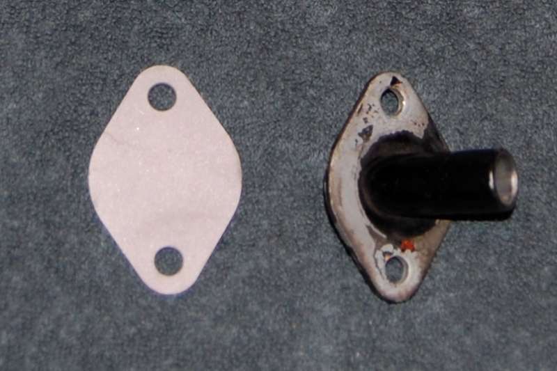
First up I removed the pedal, firewall pivot, and all the linkage up to the carburetor. The nutserts in the floor were plugged with silicone sealant followed by a pair of 1/4x20 button head Allen screws. Using the bellcrank pivot mount as a template, a block off plate (the same thickness as the pivot plate) was fabricated to cover the pivot hole:
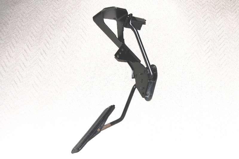
This is what the complete 71-72 pedal assembly looks like before modifications:
The upper chunk was quickly unbolted and the trusty Dremel tool was called on to slice off the attaching bracket, level with the top of the plastic firewall anchor:
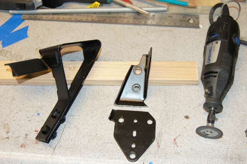
After further study I could find no reason to retain the ear on the upper left side, so it was sliced off and the remaining part angled to more closely match the other side:

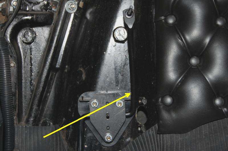
Early test fittings indicated the right side of the plastic mount should be ground flat to match the angle of the firewall. This picture is out of sequence because it shows all three mounting bolts, but its the only one showing where the plastic mount was modified:
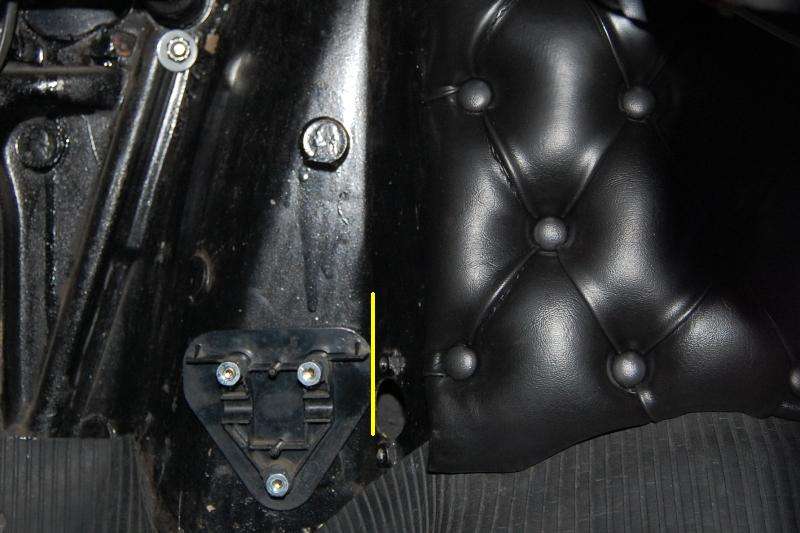
The complete assembly was test fit numerous times looking for the best fit at the firewall, the most comfortable pedal position, and level alignment. (Some of the pictures appear to lean to the left, but thats because I didnt have the camera level on the seat). Once the location was established, the upper right hole was marked with a 17/64 transfer punch (the next size up from ¼). It was a tight slip fit to keep alignment accurate. That hole alone was drilled to ¼, and the complete pedal assembly reattached to the firewall. The allowed a precise final alignment before marking the other two mounting holes.
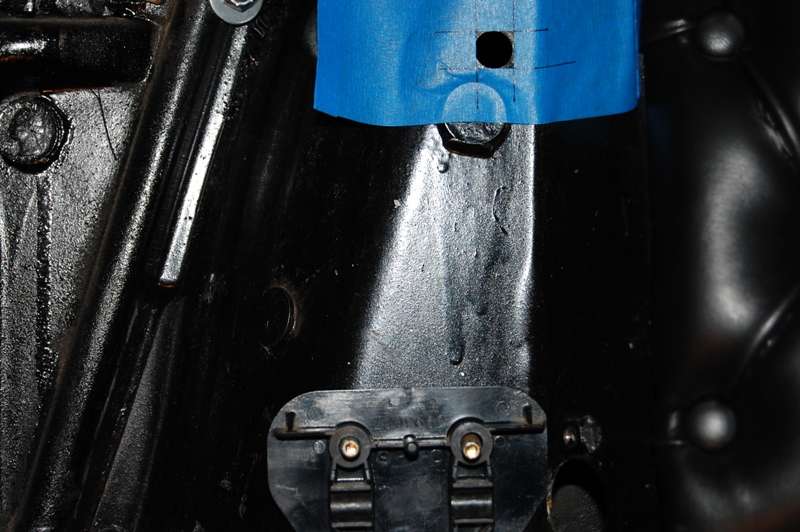
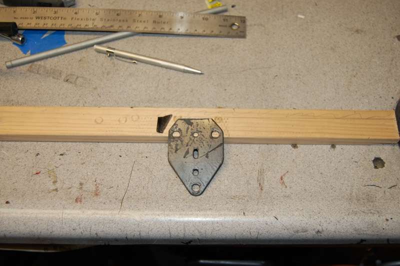
With the pedal where it belonged, the top of the bellcrank needed to move about ½ to the left. It was clamped in the bench vise at the point indicated by the arrow, and given a gentle nudge with an 18 adjustable wrench. Bolted back in place, the upper cable hole was marked with a 5/32 transfer punch directly through the cable restraint bushing:
And finally the cable hole was drilled out to ½.

To help insure the cable hole came out square and level, I started out by making a template/guide. I applied a length of 2 masking tape to one of my wifes cutting boards. A ½ square was marked and cut out freehand with an Xacto knife.

It was lined up and stuck over the 1/2 hole: