I have one for the 64 so I will post it up. the wires are generally as follows.
1. Green--temperature sensor wire to temp light in dash or to temperature gauge. It looks like the far left in your picture.
2. Pink and Tan small wires to the fuel gauge, The pink goes to the fuse panel and the tan goes to the fuse panel and then to the fuel tank sender.
3. The gray wires are just the dash light wires. The light blue and dark blue on the 64 dash are for the directional signals, I'm not sure what the dark blue wire is on your dash.
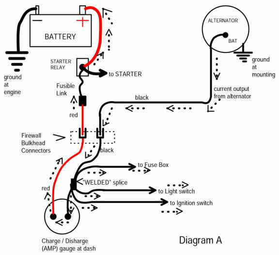
4. Now her is a big difference between the two. All the positive power to your truck goes through the amp meter and there should be two large wires running to it. The fourth diagram shows how it is wired. I think the 63 was the last year this style amp meter was used. The 64 diagram shows a charging light in the diagram I posted. It looks like the amp meter in your attachment has the red and black wires going to it.
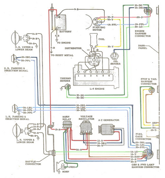
This is the engine diagram. If you follow the wiring colors you can see where they go. Green to temp and dark blue if you have a light is the oil light.
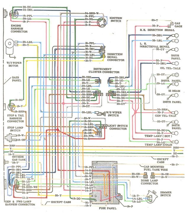
This is the fuse panel and cab diagram. If you follow the pink and tan wires from the gauge lights back to the fuse panel you can see where they go.
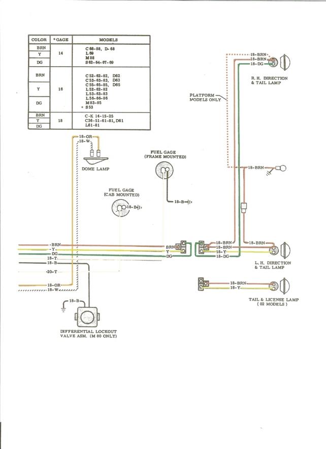
This is the wiring to the tail lights and the fuel tank sender which is a tan or light brown wire.
This is the old style amp meter wiring which will have large wires on each side of the amp meter. The main thing to remember is that both these wires are positive and do not hook a ground to either side or the harness will burn up, or worse.