Quote:
Originally Posted by k1rodeoboater

I found a page where they talked about how the 47ohm resistor will only be accurate at full and empty, everywhere else along the scale it won't be accurate. It was something to do with how the sending unit works. I'll see if I can dig it up. DocVette's response is the only one where I've encountered the use of a pot to convert down to the correct ohm range. I'm willing to try his idea out but I'm no electircal guru when it comes to making curcuits or anything like that. When it comes to electrical I'm basically a caveman. I can run wires, crimp connectors, solder connections, and read wiring diagrams...but ask me any specific technical stuff I'll give you the o.O look.
Is this the correct pot that I'll need?
http://www.radioshack.com/product/in...ductId=2062355
As for wiring it up it should look something like this correct?
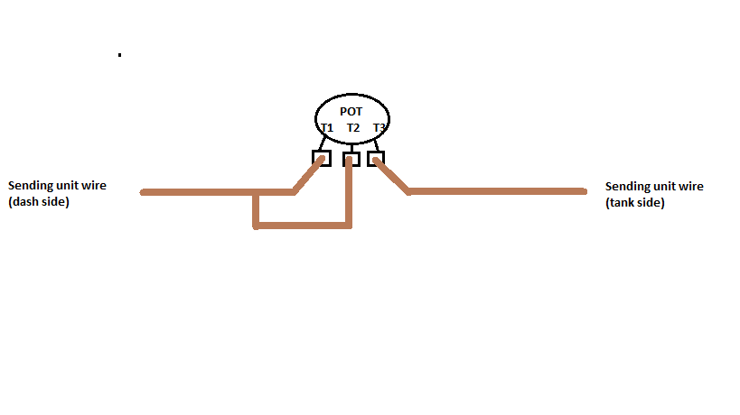 |
C/P from Docvette----The pot or resistor goes in the sender wire, Cut it and attach one end to the resistor, and attach the other end to the other end of the resistor or pot..
On a pot, Terminals 1 and 2 tie together with one end of the wire, and terminal 3 gets the other end of the wire..
The Sender is what provides the ground through It's own "Variable Pot" on the float arm, to ground..one side of the sender is on ground the other is the sender information wire (to gauge) You are adding resistance to that wire by adding a resistor or pot..to balance the system to 90 ohms.
ME-----It doesn't seem to matter going by the bolded which leg the middle is paralleled with,