This thread has been inactive for a while but there is some information that I would have liked to have that I found missing. So here goes:
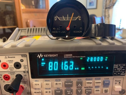
Yes, it is an external shunt ammeter circuit. Looking at a samle size of one, so keep that in mind. The meter itself looks to require about 800mA of current to move 1/2 scale in either direction. The response looked pretty linear, I'd expect double that for full scale deflections. I did not dare run 1.5A through that 50 year old fine wire.

The 12AWG red wire from the junction block to the voltage regulator connector measured 30mOhms using a 4 wire meter. I did not want to unravel to expose the splice, the regulator connection should be close enough.
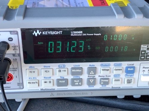
You end up with a low resistance ammeter path in parallel with a lower resistance wire path. A lot of current would need to run through that 30mOhm wire to deflect the needle. I will take a reading from the junction block to the voltage regulator connector with the red wire disconnected from the junction block to get the installed ammeter path resistance once I put it all back together. Cleaning up the instrument cluster now.
From a practical point of view, you have to make sure that ALL of the connections from the junction block, through the ammeter, through the fuses and to the splice are solid. Any added resistance in the ammeter path will cause a lower deflection than desired or expected.