Quote:
|
There are so many versions of the Mini wiring diagrams that it's hard to determine what does what but I've figured out most of the column wiring. There are 3 wires that go from the column to the wiper motor. There is ONE wire for left turn, ONE wire for right turn, Headlight brights, Headlight main, and horn. There is one remaining wire and I think/hope it is the wire that brings power to the column. Not sure though and not sure how to determine if that's the case except to remove the steering wheel and check which wires go to the turn signal switch.
|
So you have the dimmer and wiper switch on the column? Is that also the turn signal switch lever? I assume it is.
First off, the wires for the wiper motor on the GM trucks that run from the wiper motor to the wiper switch in the GM dash which are going to go to your steering column, are all ground wires. The wiper speeds and the windshield wash are all swiched on the ground side. So do not run any power wires to them into the column until you find out if the Mini is switched the same way.
The power to the wiper motor, on the GM truck wiper motor, is delivered by a yellow wire from the wiper fuse on the fuse panel to the power terminal on the wiper motor. It's a two speed motor on the GM truck, what you got on the mini?
We'll leave it there for now on the wiper motor.
Getting on to the headlight dimmer switch. The Gm harness has a blue wire from the headlight switch that carries power to the dimmer switch on the left floorboard. It gets 12 volts when the headlight switch is turned on, key on or key off don't matter.
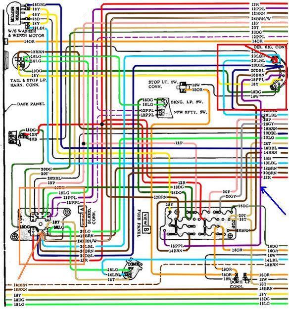
This diagram shows the dimmer switch in the very bottom center with the blue wire coming in from the headlight switch. You can see the light green and tan wires coming off the dimmer. Those are the bright and dim headlight wires respectfully.
Looking in the upper left top edge is the wiper motor, with the yellow wire from the power terminal and the light blue and dark blue wires that go to the wiper switch for the two speeds on the motor. There's also another black wire that goes to the washer terminal on the wiper switch.
if you look closely at the yellow wire on the wiper motor you can see that it joins the ground wire for the wiper speed or the washer. THIS IS WRONG!!!!
It is wrong on the diagram but the manual shows it on the center terminal by itself with a loop over to the slow speed winding. Whoever drew this diagram got it wrong. I have the correction in another diagram for later.
Here is the diagram of the headlight switch that shows the blue power wire going to the dimmer switch. It is in the bottom right. Refer back to the first diagram for clarity.
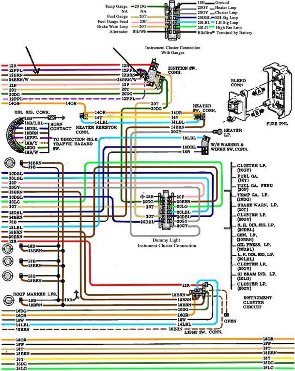
I would check the one wire that you have with a voltmeter for continuity with the main and bright wires. If it is the power in, wire for the column dimmmer switch, it will have continuity with one of them and not the other,and when you actuate the dimmer switch it should have continuity with the opposite wire and none with the other. If it works that way then you will have to match the wires with the blue, green, and tan wires from the GM harness.
The other possibility is that this wire is the power in wire for the turn signals and you can test this the same way with the voltmeter, by checking continuity between it and the two turn signal wires by moving the lever to left and right turn positions. If it works out to be the turn power wire, then it will be matched to the purple wire in the GM harness that powers the turn signal switch in the GM column.
Quote:
|
Turn signals: I'm going to splice together from the GM column harness the front and rear left and front and rear right and split those and join them to the two turn signal wires in the Mini column harness and the hazard switch. For the stop switch wire (white) going to the column, I'm going to wire my taillights separate from the brake lights and run this wire to the back. Disconnect yellow and green wires and run these to the defined turn lights. Then connect the brake/turn filament together and run separate wire to the white stop light wire going to the column. Correct?
|
You'll have a couple of problems with this setup.
First if you wire the front and rear turn signals together your turn signal will work ok ,but when you step on the brake all four lights will come on. You'll have front and rear brake lights LOL.
Remember the hazard wire is a separate wire than the turn signal wire and it sends power to the T/S switch which sends power to all four lights.
Are your tail lights separate from the brake/turn lights or do you have all three in the same bulb like the GM bulbs?
The GM tail lights get power off the head light switch via a brown wire.
This brown wire is fed by an orange wire from the fuse panel which also feeds the brake light switch and the dome light on the GM trucks.
SEE BELOW
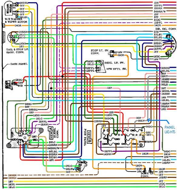
The orange wire is hot, key on or key off, so the brakes and dome will work without the key on. Looking at this diagram shows the orange wire coming to the headlight switch, and also the brown wire leaving the switch to power the tail lights and the front parking lights.
The other problem you'll have is that when you put either turn signal on, and the brakes are also on, the brake light on the corresponding turn side is cancelled out. This is done with the switching pins in the turn signal switch. If you have separate turn lights on the Mini, then you can run the wires like you said, and then run the brake and tail lights together in another bulb.
OK what's next. Oh yeah the horn. Do you have a horn relay? The wiring is simple. GM runs three wires to the relay. Red, green and black.
Red is power from the battery, green goes to the horn,and black is the small wire that goes to the column.
Inside the relay is a coil and a set of points. The red wire powers the coil and when the coil is energized by grounding the small black wire, the points close, and the red wire powers the green wire to the horn and it blows.
Hope I've helped.