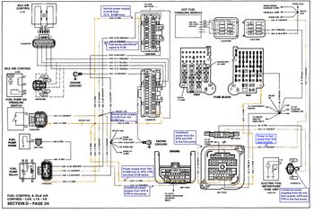
Below are the entire combined 440 ORN & 120 TAN/WHT circuits, mapped out from the fuse block to one of the fuel pumps. The 120 circuit is included because, when the OPS or FPR contacts are closed, it becomes an extension of the 440 circuit. Consequently, in addition to the 440, a short circuit in the 120 will also cause the 10A ECMB fuse to blow.
440 ORN circuit starts at the fuse block (10A ECMB), then goes into the engine compartment and feeds both of the fuel system controls (OPS/FPR) used with L19 applications. It also goes to both banks of the ECM - as the fused power supply:
The power coming out of the controls is now carried on the 120 TAN/WHT lead. The 120 passes through the firewall and back into the cab. Once inside the cab, the power from the hot fuel handling module is also spliced into the 120 TAN/WHT circuit.
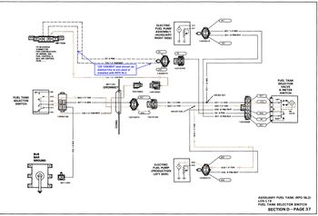
With dual tank applications, that tan/wht wire doesn't go all the way to the fuel pump. It ends at the tank select switch. The power out of the switch will be carried on either a tan or gray wire - depending on switch position. Both the tan and gray leads then pass through the firewall and continue on back to the pumps/transfer valve.
Which ever one of those conductors that is connected to the tan/wht- through the switch contacts - is the one that will provide power to the fuel pump. It will be switched so that power from the 120 will go to the positive side of the corresponding pump windings. The other wire will be connected to the negative side of the pump windings - and the other end will be connected to the main ground bus (via the select tank switch).
The same hot lead used to power the pump will also provide a polarized power supply to the transfer valve's operating coil. When the coil is energized, the internal plumbing will be shifted to the active tank (i.e. the one with the online pump).
Finally, in addition to energizing the appropriate pump and shifting the valve over to the active tank, when the position of the select switch is changed, one other thing happens . The sensing leg for the fuel tank gauge is also shifted to the active tank. There is no power involved in this process, the contacts for the tank level indication are directly coupled to the transfer valve internals. So, when the valve rotates and changes the fuel supply from one tank to the other, the sensing gauge's leg moves along with it.
The single sheet wiring diagram for the 440 and 120 circuits:
The wiring diagram for RPO NL2 (dual tanks):