
|
Register or Log In To remove these advertisements. |
|
|
|
|||||||
|
|
Thread Tools | Display Modes |
 02-05-2013, 09:02 AM
|
#1 |
|
Registered User
Join Date: Jan 2013
Location: Leonardtown, MD
Posts: 1,633
|
To read further discussion on this topic go here- LINK
A couple years ago I helped with a metalshaping demo in Berryville VA, where the focus was to be on hand tools so that anyone could duplicate the results inexpensively. I didn't get as many pictures of the event as I normally would with my typical tech threads done from my shop, (too many hammers in my hands) so this will be supplemented with some diagrams to make a good tech thread. Your typical Lancaster type shrinker stretchers are in the neighborhood of 150+ and as we are trying to show these skills using "cheap" tools, this thread will discuss tuck shrinking. For the demo, I started with a 12" long panel with a 1-1/2" wide flange bent on the long edge. Then discussed some of the issues faced when shrinking a flange. For demonstration purposes, in the following pictorial we have a 12" long panel with a 1-1/2" wide flange.  If we were to look at the same panel with a radius, formed by shrinking the flange, we would note dimensions similar to as follows:  ....where the 90 degree bend at the flange still retains its 12" length, the centerline of the flange in this case is shortened by almost an inch, and the outer edge of the flange shortened by almost another inch. In working with the Lancaster/Eastwood style shrinker-stretcher machines, it is important to note that they are a linear device, the movement they introduce into the metal is in a straight line.  So that once a radius starts to form, and with the shrinking device still moving in a linear fashion, the outer edge of the flange will be put into tension as the centerline shrinks. Anyone who has used these devices will have seen this as the machine starts to lose its effectiveness.  To counter this effect, we need to shrink the outer edge of the flange more than the inner. By simply alternating the depth of the shrink as shown, you can provide more shrink to the outer edge and the device will become more effective.  Another method of shrinking is with the use of tucks. Looking at their shape, the tuck has a wider "gather" at the edge of the flange as compared to the inside bend of the flange, so this eliminates some of the tension issues seen in the mechanical shrinker.  Where the demo was to concentrate on using only hand tools so that the participants could readily duplicate the results without the need for a major purchase, we did find the use of the Shrinker a good comparison, and by chance the tuck shrinking did prove to be faster and more effective for the wider flange we were using. For the tuck shrinking, one can use tucking forks, rounded jaw pliers (by design or modification) or special designed devices. As an example, here is a set of tucking forks I made out of some scrap metal and 5/8 bolts turned down.  And a pair made from needle nose pliers..  Probably the biggest challenge with using either of the above tools is producing consistent tucks. To produce a flowing, consistent radius, we should start with consistent tucks, both in size and the spacing between them. I decided to make a pair of tucking pliers out of Vice Grips, as the jaw adjustment on them would prove to give repeatable sized tucks. We'll start off by finding a pair of vise grips suitable for the job, which in this case means the jaw serrations are starting to wear and round off and won't grip much of anything else. Finish what has started by removing the serrations to produce a nice flat jaw on the bottom, and cut the top one off at about 30 degrees from its original position.  I had some extra long shouldered 3/8 bolts, perfect round stock for the job. Three of them were cut off to 1-1/2" length.  Here's my economy model lathe made by Dewalt...  To set the spacing for the "fingers" the first is clamped in the vise grip jaw, centered. 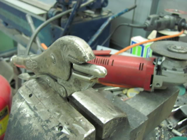 The outer is placed next to it and then welded down the outside, center finger removed, and then welded down inside. Here we should leave a slight gap of your sheet metal thickness to prevent any binding, which will allow a deeper tuck.    Repeat for opposite side, then weld center finger.   Note in the above picture the 30 degree cut of the upper jaw positions the center finger at an angle compared to the bottom fingers. It is this angle that will help to form the tuck's shape. Of course I took my favorite anvil along to the meet, here clamped in the vise..  Again our object in this case is consistency, so equally spaced marks are placed on the flange, identical tucks made at each mark, and you can see the consistent radius along the panel.    I use a O/A torch to heat the tucks prior to hammering them flat. Others prefer to not use heat, and can capture the tuck and flatten it very effectively without it. I am still working on this proficiency, so in the meantime, I use heat. We're looking for something like this, prior to hammering.  Here OJ assists with torch duties...  Another point to mention is that the hammering action tends to also spread the tuck back apart if not captured effectively. Where the picture above doesn't show it well, a good means of overcoming this would be to clamp a strap of metal across the ends of the newly formed radius prior to hammering, similar to this:  Then the hammering force will be more effective in flattening the tuck back into itself. 
__________________
Robert Last edited by augie; 06-16-2013 at 12:43 AM. |

|
|
02-05-2013, 01:28 PM
|
#2 |
|
Registered User
Join Date: Jan 2013
Location: Leonardtown, MD
Posts: 1,633
|
Modified/re-purposed vise grips
Had someone stop by the shop needing to add a bead to the end of the aluminum tubing (fuel fill) he had to install in his Cobra project. He had trimmed one end for a better fit and needed to replace the bead for the hose...
 ......to match the other end.  The dies on my bead roller were much too large in diameter, so I thought to make a manual device out of a pair of vise grips... Once the teeth start to wear these make ideal candidates for purpose-built tools. For the punch part of the tool, started with a thick 5/8 washer and gave the edges a nice radius in the lathe.  The vise grip bottom teeth were welded in and sanded smooth to provide a flat area for the punch to push against without so much marking of the tubing, then an 1/8" thick 3" dia cut off wheel provided the recess in the lower jaw of the vise grips.  The washer was notched and bent to better fit the vise grips for welding....    Multiple layers of masking tape added to use as a reference/stop mark to align against end of vise grip jaw. The masking tape worked well to provide a reference stop and not scratch the polished aluminum, like a hose clamp might.  The vise grips with their adjustable jaw setting work well to set the tension, clamp on the tubing every 1/4 inch or so, making one complete revolution around the tube, then adjust tighter and repeat as needed...  Finished product....   A nice tool for less than $15, just right for a one time or limited use. Feel free to add what modification you've done with your vise grips...
__________________
Robert Last edited by augie; 06-16-2013 at 12:38 AM. |
|
|
|
02-05-2013, 01:40 PM
|
#3 |
|
Registered User
Join Date: Jan 2013
Location: Leonardtown, MD
Posts: 1,633
|
Re: Modified/re-purposed vise grips
Thanks, here's one more......
Probably one of the biggest challenges in taking things apart for repairs is doing so without inflicting more damage. Many times a door will require work to the inner structure as well as the outside. In such a case, it may be easier to leave one side intact while repairing the other, to keep a reference to work against. Here the Vice Grips lower jaw is modified to receive the edge of the door skin...  Then a suitable "blade" is found....   Some welding and grinding, and we have a new body tool..... The blade was aligned to be centered in the groove of the lower jaw. 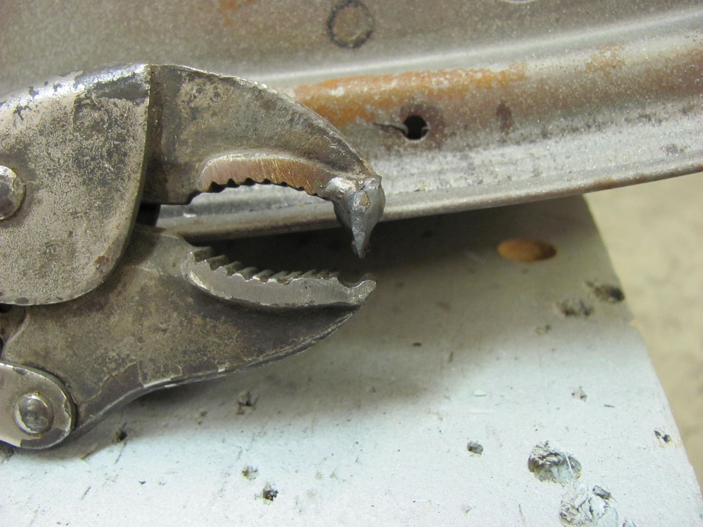   Starting at the corner, a diagonal slice is made in the inner panel so it will remove easier... 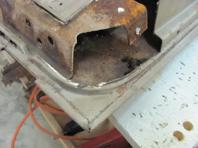 ....and the tool is used to gently pry up on the flange of the tailgate skin.....    In the case where you may be reusing the outer skin and only replacing the inner, spot welds can be removed by a rounded end burr grinder, in an attempt to keep the damage (and hole diameter) to the skin flange at a minimum. Continuing:  The Vise Grip's adjustable tension help to keep the "unbending" consistent across the panel, for an easier "recrimping" if the outer will be reused.   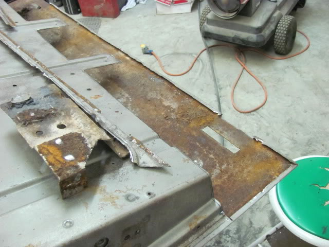 All ready for replacing the inner.........
__________________
Robert Last edited by augie; 06-16-2013 at 12:41 AM. |
|
|
|
02-05-2013, 02:21 PM
|
#4 |
|
Registered User
Join Date: Aug 2012
Location: On the banks of the Clackamas River, Eagle CreeK Oregon
Posts: 387
|
Re: Modified/re-purposed vise grips
Have you made a panel flanging tool ?
I want to replace a couple rust-outs in body panels , I have been trying to come up with a plan for a tool to recess the flange 
|
|
|
|
02-05-2013, 02:42 PM
|
#5 |
|
Registered User
Join Date: Jan 2013
Location: Leonardtown, MD
Posts: 1,633
|
Re: Modified/re-purposed vise grips
I haven't made one with the vise grips as I tend to butt weld all my patch panels. I do have dies for my bead roller that will do a step flange, used them in producing the windshield panel for a Task Force truck where it sits behind the flange of the roof panel.... May need to post that thread up as well...

__________________
Robert Last edited by augie; 06-16-2013 at 12:42 AM. |
|
|
| Bookmarks |
|
|


 Linear Mode

