
|
Register or Log In To remove these advertisements. |
|
|
|
|||||||
 |
|
|
Thread Tools | Display Modes |
 02-15-2011, 11:22 PM
|
#1 |
|
Registered User
Join Date: Nov 2010
Location: Fayetteville NC
Posts: 752
|
converting a 90ohm sender to a 30ohm sender
I'm installing a 69 camaro tank into my C10...only problem is the sender that comes with the tank is a 90ohm unit and I'm fairly certain my truck uses a 30ohm unit (some 66's apparently had 90's on occasion, I haven't checked mine yet). Do any of you have any good ideas how to go about doing this aside from a 47ohm resistor wired in parallel across the sending wire and ground wire? I'd like to have a linear gas gauge using my stock cluster. The only other idea I've found on the net was to use a 50ohm linear taper pot placed on the sending wire (can be mounted anywhere) but I've not been able to find any info on it to know if it'll still be linear.
I don't want to replace my dash cluster or get a new gauge unless absolutely necessary. |

|

|
|
02-16-2011, 09:09 AM
|
#2 |
|
Msgt USAF Ret
  Join Date: Jan 2005
Location: Kalamazoo, Michigan
Posts: 8,703
|
Re: converting a 90ohm sender to a 30ohm sender
I have not tried this but here is an old thread from another forum on it. They mention a 100 ohm taper pot wired in line with the sending unit wire.
http://www.hotrodders.com/forum/gm-f...hm-106069.html
__________________
VetteVet metallic green 67 stepside 74 corvette convertible 1965 Harley sportster 1995 Harley wide glide Growing old is hell, but it beats the alternative. |
|
|
|
|
02-16-2011, 10:42 AM
|
#3 | |
|
Registered User
Join Date: Nov 2010
Location: Fayetteville NC
Posts: 752
|
Re: converting a 90ohm sender to a 30ohm sender
Quote:
|
|
|
|
|
|
02-16-2011, 11:21 AM
|
#4 |
|
Msgt USAF Ret
Join Date: Jan 2005
Location: Kalamazoo, Michigan
Posts: 8,703
|
Re: converting a 90ohm sender to a 30ohm sender
In another part of that same forum another guy says he wired the 47 ohm from the sender terminal to the ground flange for a parallel resistance and it worked fine. Doc Vette on the first page said the taper pot worked just wired in series with the sender wire and the sending unit terminal. I can't see why the pot would work if the fixed resistor won't.
In fact I never thought any fixed resistor would work because, while the tank sender variable resistor would be on zero the fixed resistor would still put 47 ohms on the 90 ohm gauge and to a 90 ohm gauge that means a half a tank of gas. If the taper potentiometer drops resistance in a ratio with the variable tank sender then I can see where, as the resistance on the variable resistor in the tank drops to zero the resistance on the taper pot drops proportionally and equals zero at the same rate so that they are both on zero at the same time, it would give a zero resistance to the gauge for a tank empty reading. This has my curiosity up so I am going to do a little research on it. BTW the old guy in the forum, Doc Vette passed away so we can't ask him.
__________________
VetteVet metallic green 67 stepside 74 corvette convertible 1965 Harley sportster 1995 Harley wide glide Growing old is hell, but it beats the alternative. |
|
|
|
|
02-16-2011, 01:04 PM
|
#5 |
|
Registered User
Join Date: Nov 2010
Location: Fayetteville NC
Posts: 752
|
Re: converting a 90ohm sender to a 30ohm sender
I found a page where they talked about how the 47ohm resistor will only be accurate at full and empty, everywhere else along the scale it won't be accurate. It was something to do with how the sending unit works. I'll see if I can dig it up. DocVette's response is the only one where I've encountered the use of a pot to convert down to the correct ohm range. I'm willing to try his idea out but I'm no electircal guru when it comes to making curcuits or anything like that. When it comes to electrical I'm basically a caveman. I can run wires, crimp connectors, solder connections, and read wiring diagrams...but ask me any specific technical stuff I'll give you the o.O look.
Is this the correct pot that I'll need? http://www.radioshack.com/product/in...ductId=2062355 As for wiring it up it should look something like this correct? 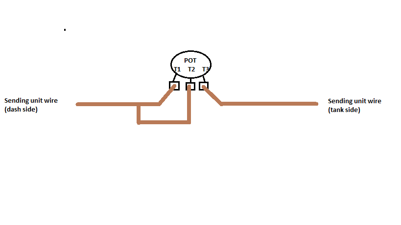
|
|
|
|
|
02-16-2011, 01:42 PM
|
#6 | |
|
Registered User
Join Date: Dec 2008
Location: Yay Area CA
Posts: 2,329
|
Re: converting a 90ohm sender to a 30ohm sender
I may have interpreted Docvette incorrectly but I think he was going from 30 ohm to 90 ohm and not 90 ohm to 30 ohm. The formula for resistors in series is R=R1+R2 so any resistance placed in series is added to the 90 ohm. But resistors in parallel is R= R1x R2 / R1+R2 so 90 x 47 / 90 + 47 = ~30.87 ohm, but it wont be lineal because at 1/2 tank @ 45 ohm parallel with 47 ohm you get ~23 ohm which is about 3/4 tank on the 30 ohm system.
__________________
1965 GMC shortwide big window 1969 Chevy C20 long (for now) 2005 Silverado 2500HD Crew Cab Quote:
|
|
|
|
|
|
02-16-2011, 02:12 PM
|
#7 | |
|
Msgt USAF Ret
Join Date: Jan 2005
Location: Kalamazoo, Michigan
Posts: 8,703
|
Re: converting a 90ohm sender to a 30ohm sender
Quote:
Therein lies the problem where the setup is not very accurate.
__________________
VetteVet metallic green 67 stepside 74 corvette convertible 1965 Harley sportster 1995 Harley wide glide Growing old is hell, but it beats the alternative. |
|
|
|
|
|
02-16-2011, 02:29 PM
|
#8 |
|
Msgt USAF Ret
Join Date: Jan 2005
Location: Kalamazoo, Michigan
Posts: 8,703
|
Re: converting a 90ohm sender to a 30ohm sender
The answer in the forum is to use a 50 ohm pot of 5 watt rating. I have not found any thing to change the resistance of the pot without changing the shaft setting .
I remember awhile back I did make up a tester for the fuel and temp gauges and I used a pot in series with the ground wire. It worked fine as long as I moved the shaft the needle would deflect. It didn't work perfectly because the ohms weren't correct. all I was looking for was needle deflection so it was fine for testing. I wish now I had placed a 30 ohm resistor in the circuit and tried to make it work.
__________________
VetteVet metallic green 67 stepside 74 corvette convertible 1965 Harley sportster 1995 Harley wide glide Growing old is hell, but it beats the alternative. |
|
|
|
|
02-16-2011, 02:52 PM
|
#9 | |
|
Msgt USAF Ret
Join Date: Jan 2005
Location: Kalamazoo, Michigan
Posts: 8,703
|
Re: converting a 90ohm sender to a 30ohm sender
Quote:
On a pot, Terminals 1 and 2 tie together with one end of the wire, and terminal 3 gets the other end of the wire.. The Sender is what provides the ground through It's own "Variable Pot" on the float arm, to ground..one side of the sender is on ground the other is the sender information wire (to gauge) You are adding resistance to that wire by adding a resistor or pot..to balance the system to 90 ohms. ME-----It doesn't seem to matter going by the bolded which leg the middle is paralleled with,
__________________
VetteVet metallic green 67 stepside 74 corvette convertible 1965 Harley sportster 1995 Harley wide glide Growing old is hell, but it beats the alternative. |
|
|
|
|
|
02-16-2011, 03:05 PM
|
#10 | |
|
Msgt USAF Ret
Join Date: Jan 2005
Location: Kalamazoo, Michigan
Posts: 8,703
|
Re: converting a 90ohm sender to a 30ohm sender
Quote:
The pot would go in the sender wire from the variable resistor. This is starting to make my head hurt LOL
__________________
VetteVet metallic green 67 stepside 74 corvette convertible 1965 Harley sportster 1995 Harley wide glide Growing old is hell, but it beats the alternative. |
|
|
|
|
|
02-16-2011, 03:44 PM
|
#11 | |||
|
Registered User
Join Date: Nov 2010
Location: Fayetteville NC
Posts: 752
|
Re: converting a 90ohm sender to a 30ohm sender
From DocVette....he actually describes how to do BOTH 30 to 90 and 90 to 30 conversions in that thread. LOL no wonder why this is causing some of the confusion and headache.
The original post is asking how to convert a 90 ohm sender to work in a 40's era Chevy which has a 30 ohm gauge. The OP refers to this thread in the first post.....http://www.oldengine.org/unfaq/oddbits.htm...but more specifically this part Quote:
Quote:
Quote:
...I think....I didn't get much sleep last night so my logic may be off. |
|||
|
|
|
|
02-16-2011, 07:24 PM
|
#12 | |||
|
Registered User
Join Date: Dec 2008
Location: Yay Area CA
Posts: 2,329
|
Re: converting a 90ohm sender to a 30ohm sender
Quote:
 . .Quote:
No matter what you use it should go in parallel and not series. the pot may start out as adjustable but once it is set and wax or other sealant is applied to the stem it's just a fixed resistor at that point. It's true that you will only be accurate at full and empty because as the fuel level goes down so does R1 which means the value of R2 would need to change to give you a proportionate resistance which we know cant happen because R2 is fixed at ~ 47 ohms. Example at 3/4 of a tank on a 0-90 ohm sending unit the resistance is 67.5 ohm and on a 0-30 ohm sending unit it's 22.5 to get a correct reading on the gauge it would take about a 34 ohm resistor in parallel with the 67.5 to equal 22.5. Below is a chart of the actual fuel level compared to gauge reading with this mod. the accuracy is based on theory and subject to my math but it will give you an idea of whats happening.
__________________
1965 GMC shortwide big window 1969 Chevy C20 long (for now) 2005 Silverado 2500HD Crew Cab Quote:
|
|||
|
|
|
|
02-16-2011, 07:58 PM
|
#13 |
|
Registered User
Join Date: Nov 2010
Location: Fayetteville NC
Posts: 752
|
Re: converting a 90ohm sender to a 30ohm sender
Here's another question to throw into the mix...if I don't wax/glue to pot will it self adjust and be linear or is it one of those you manually have to do it sorts of things?
Like I said I'm an electrical theory noob...sorry for the dumb question. Also if I'm reading your graph correctly, and boy do I sure hope I am or my old math teachers are gonna kick my butt, the actual fuel level will be higher than what the gauge is reading across the spectrum. If that's the case that's really all that I care about more than anything. I don't want to have my gauge reading higher than what it really has in the tank leaving me stranded on the side of the road. |
|
|
|
|
02-16-2011, 08:12 PM
|
#14 | |
|
Registered User
Join Date: Dec 2008
Location: Yay Area CA
Posts: 2,329
|
Re: converting a 90ohm sender to a 30ohm sender
The pot wont self adjust you would have to do it manually but you will never know where you are once the settings are changed.
Yeah according to the chart you'll have more gas than the gauge indicates but the chart was made on the assumption that the stock sending units are both lineal
__________________
1965 GMC shortwide big window 1969 Chevy C20 long (for now) 2005 Silverado 2500HD Crew Cab Quote:
|
|
|
|
|
|
02-16-2011, 08:25 PM
|
#15 |
|
Registered User
Join Date: Nov 2010
Location: Fayetteville NC
Posts: 752
|
Re: converting a 90ohm sender to a 30ohm sender
OK just to check to make sure I'm not completely retarded....
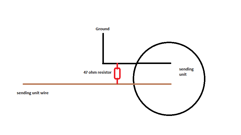 that's how it should be...right??? as a side note...I REALLY need to make sure I get a good night's rest before I attempt this install. I've been space cadeting like crazy all day. |
|
|
|
|
02-17-2011, 12:34 PM
|
#16 | |
|
Registered User
Join Date: Dec 2008
Location: Yay Area CA
Posts: 2,329
|
Re: converting a 90ohm sender to a 30ohm sender
That should do it. It's always a good idea not to have any distractions when wiring or trouble shooting but as far as circuits go this one is almost impossible to screw up the worst that can happen is either you short or open the circuit and in this case that just means the gauge will either go to empty or full either way you'll known what the problem is and nothing gets damaged.
__________________
1965 GMC shortwide big window 1969 Chevy C20 long (for now) 2005 Silverado 2500HD Crew Cab Quote:
|
|
|
|
|
|
02-17-2011, 12:48 PM
|
#17 |
|
Msgt USAF Ret
Join Date: Jan 2005
Location: Kalamazoo, Michigan
Posts: 8,703
|
Re: converting a 90ohm sender to a 30ohm sender
I second that, if you recall one of the guys in Docvette's forum suggested running the resistor from the sending unit terminal to the ground flange on the sending unit. That's the same thing you have in the drawing, only a little further from the sending unit. Be sure and give us feedback on it. This one don't come up very often and it would be nice to have an answer. VV
__________________
VetteVet metallic green 67 stepside 74 corvette convertible 1965 Harley sportster 1995 Harley wide glide Growing old is hell, but it beats the alternative. |
|
|
|
|
02-17-2011, 01:17 PM
|
#18 |
|
Registered User
Join Date: Nov 2010
Location: Fayetteville NC
Posts: 752
|
Re: converting a 90ohm sender to a 30ohm sender
Will do. I'll be linking back to this thread in my build thread and the 60-66 C10 section as well as updating here after I get it all installed.
As usual I've over thought the whole thing...but that's not always a bad thing. At least it's so easy even I can't screw it up
|
|
|
|
|
06-04-2011, 02:16 AM
|
#19 |
|
Registered User
Join Date: Jun 2011
Location: Empire, CA
Posts: 1
|
Re: converting a 90ohm sender to a 30ohm sender
Gentlemen rather than letting you bask in your odd desire to increase complexity may I suggest another solution to your problem.
As I understand it you have a circuit which is imbalanced. You are attempting to use a linear moment arm potentiometer of 90 ohms resistance to propel a 30 ohm gauge linear needle gas gauge. While your circuits are interesting, without logic, they cannot possibly deliver a linear response only an approximation. This is not the way, in my estimation to solve this problem. Instead, I propose a mechanical solution. Datcon manufactures 90 ohm sender units. Each degree of moment arm movement represents one ohm. Thus, 90 degrees = 90 ohms. Their float arm is 14 inches long. Suppose you were to cut off the potentiometer's moment arm from the zero position to 30 degrees. You don't cut it off mechanically, you alter the moment arm distance to achieve the appropriate tank level. For example if the fuel tank in question was 7 inches deep then one may calculate the required distance of the float through the potentiometer's moment arm quite easily. In this case the sin of 30 degrees = 0.5. Thus since sin is o/h and o = the tank depth of 7 inches it follows that h = 14 inches [how coincidental!] Thus, in such a configuration, when the moment arm of 14 inches in length floats from an empty tank to a full tank, its vertical movement is seven inches confined mechanically by the bottom and top of the tank respectively. Further there would be no more approximations. The circuit is now perfectly balanced. The earth as we know it has been restored to its orbit. This solution is elegant not only because it solves the circuit imbalances with a perfectly linear solution but it matches the aesthetics of engineering in the 1950s. In fact, I had considered calculating the angles on an old slide rule so I could appreciate the moment more fully. Sometimes mechanical solutions are the perfect solution. I would like to make one more remark. No matter how you bend your moment arm, into a pretzel if you like, as long as the distance of the moment arm is 14 inch radius and does not encumber the bottom or top of the tank through its empty full arc, it will work perfectly. And one of the other satisfactions that comes with such a design is the confident knowledge that, though concealed, your's is bigger and oh so much more sensitive, something an intelligent woman can really appreciate... again and again when going for a ride. And you will never have to worry about coming up short [dare I say again] when it really counts. |
|
|
|
|
04-01-2018, 03:28 PM
|
#20 |
|
Registered User
Join Date: Oct 2015
Location: Calgary, Alberta
Posts: 1,252
|
Re: converting a 90ohm sender to a 30ohm sender
Old thread add on post... We fabricated the stock sending unit to marry the new pick up tube and sealing flange. It took some tinkering to get the float to travel the correct range etc but the gauge reads perfectly now.
__________________
So when is this "Old enough to know better" supposed to kick in? My 1959 GMC build thread http://67-72chevytrucks.com/vboard/s...d.php?t=686989 Last edited by Foot Stomper; 04-01-2018 at 03:40 PM. |
|
|
|
|
| Bookmarks |
| Tags |
| 90 to 30 ohm sending unit |
|
|


 Linear Mode

