The 1947 - Present Chevrolet & GMC Truck Message Board Network


Register or Log In To remove these advertisements.

Go Back   The 1947 - Present Chevrolet & GMC Truck Message Board Network > 47 - Current classic GM Trucks > The 1973 - 1987 Chevrolet & GMC Squarebody Pickups Message Board

Web 67-72chevytrucks.com


Reply
 
Thread Tools Display Modes
Old 02-02-2009, 11:41 PM   #1
408cuda
Registered User
 
Join Date: Jan 2009
Location: White Creek NY
Posts: 14
Re: Tbi swap build thread

Quote:
Originally Posted by rfmaster View Post
This posting will deal with ECM side of wiring harness. A simple TBI wiring diagram can be found here:


Wow, thanks for all the effort, that's excellent!

Regarding 3rd connector - I have couple of questions - please see my list below:

3rd Connector ECM Wire Function
A A9 white/black ALDL diagnostics enable
B A5 brown/white SES light (pulled to ground by ECM)
C Empty
D A7 tan/black TCC/shift indicator (not used with std transmission)
E To RH injector, red=12v keyed power?
YES, connect to 15 Amp ECM Fuse #1 via separate relay – more on this later
F A6 pink/black 12v ECM Fuse #1 Hot in RUN/START
G Empty
H C2 Brown To air diverter valve connector.
You can ditch it if you are not using AIR pump.
J C9 Purple/white crank input needed for anything? YES
K B10 orange/black Park/neutral... this is empty on ours, had no wires coming out. OK
L ????? Purple RH o2 sensor, prpl. Not hooked up.
Does go down into engine bay? Can you find the other end?

Yes, it has the same connector as the LH o2 sensor but this one was not hooked up, ends near pass side cyl head, traces back to instrument cluster on donor (I ripped apart donor harness in truck today)


M A10 Brown VSS, brown. Did this go to the buffer under the dash?
(Yes, it went to DRAC module) But now tie to one of the two wires that will connected to after market VCC module, the other to ground
N ????? black/white Ground
P red-white Fuel pump relay, red/wht
(Which terminal of Fuel pump relay???)

Not sure which terminal but 99% positive I traced that one back to the ALDL and read it was fuel pump test.

R A8 Orange ALDL data


Since you are putting into older vehicle I would install an auxiliary relay panel (see Painless Part# 70107 Fuse Block / 7 Circuits kit http://www.painlessperformance.com/M...nstruction.pdf).
This panel would off load current that otherwise would have to travel through 50 year old ignition switch!
//RF
My friend/owner of the truck came over today and we went through his factory wiring. I was thinking we will use a new ignition switch and distribute power through it. Nothing will actually be going through his wiring this way. We have it stripped down to just a few wires left on his that we figured we can power off the new, or even existing fuse box. The items left are...

Headlights
Turn signals/brakes etc
Cig lighter
Radio
Horn

That's about all there is to this thing. There are a grand total of 4 wires going to his fuse box now! Pretty simple.

I was thinking of using the red 10g hot in from the power strip for the BAT side a switch.
Purple 10g for to starter on START terminal of said switch
A jumper from that wire to fuse block, C9 prple/wht on the other side of that fuse.
New 10g wire from ACC or RUN terminal on ignition switch to power up new fuse block.
And then my wires needing 12v in RUN can be hooked to new fuse box.

Does this sound acceptable? Like I said, I am no wiring master.

I traced a few of the unknowns left today and found the green wire was temp sender on head (was hooked on old engine) went to the gauge cluster (that was what I was unsure of on that one)
Tan that goes to nowhere, also goes to gauges
All VSS wires go into cluster harness
Blue and light green wires from trans....blue to switched hot in fuse and green doubles around and heads back out to engine bay, no clue from there but guess it's too back-up lights as cj suggested?
Also forgot brown wire last night. Goes from alt to cluster for volt gauge I reckon?
And fuel pump harness has a pink wire from pump to the cluster that I initially thought was a hot but if power is Tan/white via orange, this must have been for the fuel gauge?
The rest I think are pretty much known.

Thanks a bunch guys. Can't wait to fire her up! Going to button it up and plumb some fuel soon just to see if it will ignite. After that it gets blown apart and goes out for paint. Here is the rig it's in.


408cuda is offline   Reply With Quote
Old 
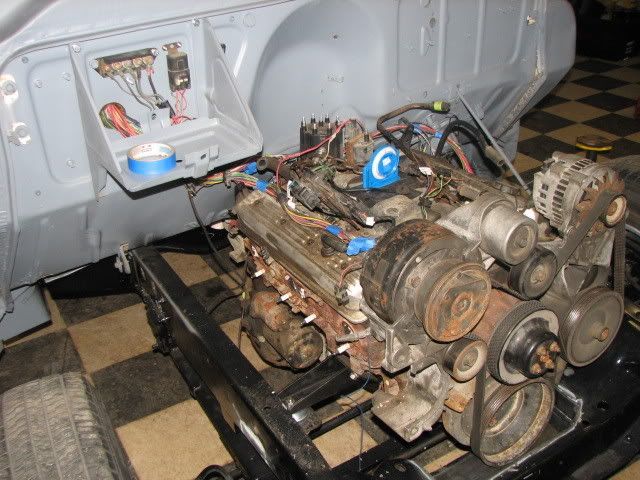
02-02-2009, 11:48 PM   #2
408cuda
Registered User
 
Join Date: Jan 2009
Location: White Creek NY
Posts: 14
Re: Tbi swap build thread

Forgot to ask. I have to relocate the knock sensor for header clearance. Is the fuel pump provision acceptable even though it's not machined or open on this block? Don't see anywhere else it will fit.

Thanks!
408cuda is offline   Reply With Quote
Old 02-03-2009, 01:45 AM   #3
rfmaster
Registered User
 
rfmaster's Avatar
 
Join Date: Oct 2003
Location: OC CA
Posts: 1,374
Re: Tbi swap build thread

CUDA

I am still drawing few more diagrams based on your last response. I think that you are almost there. Nice truck!

/?RF
__________________
"The Beast"

1975 Chevrolet C20 longbed
350/700R4! with 3inch body lift
Dual Flowmasters Super 40's!
TBI retrofit completed (2007-07-29)
New 383CID (+030) 08-304-8 9.5:1CR x36,005 (2012-12-17)
rfmaster is offline   Reply With Quote
Old 02-03-2009, 02:18 AM   #4
rfmaster
Registered User
 
rfmaster's Avatar
 
Join Date: Oct 2003
Location: OC CA
Posts: 1,374
Re: Tbi swap build thread

Quote:
Originally Posted by 408cuda View Post
Forgot to ask. I have to relocate the knock sensor for header clearance. Is the fuel pump provision acceptable even though it's not machined or open on this block? Don't see anywhere else it will fit.

Thanks!
A typical TBI system uses electrical fuel pump, which GM mounted in tank or alternatively, inline electrical fuel pump can be used instead. Typical system EFI system requires three fuel lines between tank and engine bay.
Supply line - 3/8" is used by Fuel Pump (FP) to supply fuel to TBI inlet. Please make sure that you have FP that can supply a minimum of 20 PSI. Do not go to crazy with fuel pressure as excess fuel will be bypassed and returned back to the gas tank via return line 5/16" or 3/8". Excessive fuel pump pressure tends to increase fuel temperature, which is not good - this will increase fuel vapor pressure. Third fuel line is connected to charcoal canister that connects to TBI (1/4") line.

Main DC power distribution.


//RF
__________________
"The Beast"

1975 Chevrolet C20 longbed
350/700R4! with 3inch body lift
Dual Flowmasters Super 40's!
TBI retrofit completed (2007-07-29)
New 383CID (+030) 08-304-8 9.5:1CR x36,005 (2012-12-17)

Last edited by rfmaster; 02-03-2009 at 02:51 AM.
rfmaster is offline   Reply With Quote
Old 02-03-2009, 03:06 AM   #5
rfmaster
Registered User
 
rfmaster's Avatar
 
Join Date: Oct 2003
Location: OC CA
Posts: 1,374
Re: Tbi swap build thread

Quote:
Originally Posted by 408cuda View Post
My friend/owner of the truck came over today and we went through his factory wiring. I was thinking we will use a new ignition switch and distribute power through it. Nothing will actually be going through his wiring this way. We have it stripped down to just a few wires left on his that we figured we can power off the new, or even existing fuse box. The items left are...

Headlights
Turn signals/brakes etc
Cig lighter
Radio
Horn

That's about all there is to this thing. There are a grand total of 4 wires going to his fuse box now! Pretty simple.

I was thinking of using the red 10g hot in from the power strip for the BAT side a switch.
Purple 10g for to starter on START terminal of said switch
A jumper from that wire to fuse block, C9 prple/wht on the other side of that fuse.
New 10g wire from ACC or RUN terminal on ignition switch to power up new fuse block.
And then my wires needing 12v in RUN can be hooked to new fuse box.

Does this sound acceptable? Like I said, I am no wiring master.

I traced a few of the unknowns left today and found the green wire was temp sender on head (was hooked on old engine) went to the gauge cluster (that was what I was unsure of on that one)
Tan that goes to nowhere, also goes to gauges
All VSS wires go into cluster harness
Blue and light green wires from trans....blue to switched hot in fuse and green doubles around and heads back out to engine bay, no clue from there but guess it's too back-up lights as cj suggested?
Also forgot brown wire last night. Goes from alt to cluster for volt gauge I reckon?
And fuel pump harness has a pink wire from pump to the cluster that I initially thought was a hot but if power is Tan/white via orange, this must have been for the fuel gauge?
The rest I think are pretty much known.

Thanks a bunch guys. Can't wait to fire her up! Going to button it up and plumb some fuel soon just to see if it will ignite. After that it gets blown apart and goes out for paint.
I am trying to follow what you are trying to do - it is very difficult without schematics or diagrams. Can you draw a diagram of what you are trying to do and post it. I know it is tough enough, but I am just trying to prevent shorts and burned wires and 'oh s*&*' moments!


You can relocate Knock Sensor (KS) to the other side, but it must be screwed into oil pan rail (water jacket drain plug) to be effective! KS is a calibrated microphone, tuned for a knock frequency found in a specific engine family.

//RF
__________________
"The Beast"

1975 Chevrolet C20 longbed
350/700R4! with 3inch body lift
Dual Flowmasters Super 40's!
TBI retrofit completed (2007-07-29)
New 383CID (+030) 08-304-8 9.5:1CR x36,005 (2012-12-17)
rfmaster is offline   Reply With Quote
Reply

Bookmarks


Posting Rules
You may not post new threads
You may not post replies
You may not post attachments
You may not edit your posts

BB code is On
Smilies are On
[IMG] code is On
HTML code is Off

Forum Jump


All times are GMT -4. The time now is 12:06 PM.


Powered by vBulletin® Version 3.8.11
Copyright ©2000 - 2024, vBulletin Solutions Inc.
Copyright 1997-2022 67-72chevytrucks.com