
|
Register or Log In To remove these advertisements. |
|
|
|
|||||||
 |
|
|
Thread Tools | Display Modes |
 08-26-2005, 02:49 PM
|
#1 |
|
More Cowbell....
Join Date: Mar 2004
Location: Puckett, MS
Posts: 3,569
|
No-Weld Accelerator Conversion
For anyone who wants to know, here is one way you can convert from the 'rod type' accelerator pedal which pivots on the floor, to a 'cable type' accelerator that is suspended in mid-air (mounted only to firewall)....
WITHOUT modification to your firewall. First, you will obviously have to obtain a cable type accelerator assembly, including the triangle shaped plastic mount.  Remove your existing pedal assembly and list it on the parts board. You shouldn't need it anymore! If you hold the new plastic triangle mount up to the firewall location, you will notice right away that the triangle mount will not line up with the existing holes in the firewall. You will obviously have to drill some new holes. To mark the holes, place one bolt through the upper-right hole in the mount...  Secure the mount to the firewall using the upper-right mounting hole (be sure you are INSIDE the cab)...  Now, move around to the engine side of the firewall. You should notice that the two remaining holes have nothing but plastic behind them now...  Mark through the threaded holes onto the plastic. I used a scratch awl, but a marker should work just fine...    Remove the plastic mount from the cab and verify that you can see the marks well enough to drill new holes....  Because of the threaded square nuts that are on my firewall (inside the cab), I found that the three plastic 'nubs' that are on back of the mount were in the way. I used a cutoff wheel to remove them, but a hacksaw, etc... will work also. **BE careful not to cut off the marks you just made. If you do, simply repeat the above steps to remark the location for new holes**  Now you are ready to drill the new holes. Choose a drill bit that is the same size or slightly larger than the existing holes in the mount. I chose to use a drill press, but a hand-held drill should also work...just take your time. 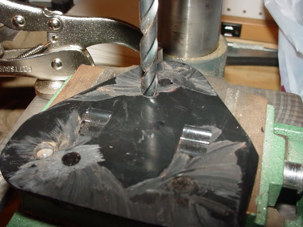 Your new holes should look something like this.. 
__________________
There once was a member from Puckett.....Who ( fill in the blank blank blank ) bucket Last edited by augie; 04-11-2011 at 11:58 PM. |

|
|
08-26-2005, 02:49 PM
|
#2 |
|
More Cowbell....
Join Date: Mar 2004
Location: Puckett, MS
Posts: 3,569
|
Now, with the new holes drilled, you can tell that the original metal cover plate is going to be too small to cover the holes.
For this you will need to create a new one out of metal. I used a scrap portion of a dash. You can use what ever you like, as long as it is roughly the same gauge as the original. Here is the original....  Original next to my new one....  Original on top of new one (for size comparison)....  New one installed over plastic mount.... 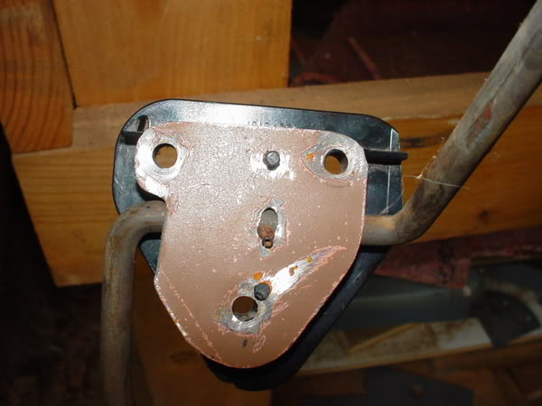 Now, reinstall the mount, pedal assembly, and metal cover in the cab. You might notice that he firewall is curved in this area, which will make it difficult to install the cable portion of the assembly. How I overcame this is to move the location of the cable to the left (towards the steering column) until it was on a flat surface. I marked and cut my mounting hole in the firewall at the same height as the hole in the pedal rod using a 1/2" drill bit, then squaring the hole off for the cable to snap into (*note-I have not made that pretty yet*). I also went ahead and mounted the cable in the newly created hole.  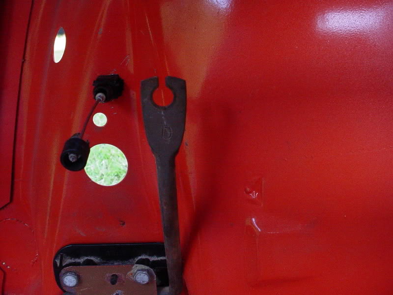 As you can see in the photos above, the hole in the firewall does not line up with the hole in the pedal rod. If you were to connect the cable to the pedal, it would be at a pretty bad angle, which could potentially cause the accelerator to stick....NOT GOOD!! All I had to do is bend the rod over to the left enough for the two holes to line up! I removed the pedal assembly and placed the pedal rod in a vice..... 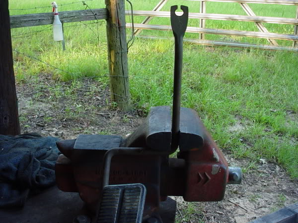 I then gave it a few taps with a hammer until I reached the correct angle...  Here is a stock one compared to the one I bent....  I re-installed everything and the holes lined up just fine. I attached the cable to the pedal assembly and tested it's movement....  "But what about the hole that is left where the rod type pedal used to go???" I just know someone is thinking that....  Well, remember, I said that was a no modification install (the hole we drilled doesn't count!).... Simply head down to the Autozone, O'Reilly, NAPA, CB Shop, or communications shop and pick up a rubber plug or a grommet. Pop that baby in there and smile at your finished project!  **If you are doing a custom job, or if you just want to take the time, you can certainly weld that hole shut with a small patch.** And I KNOW those bolts are too long. I will replace them later. But for now, they were all I had around! Thanks for watching. Tune in next time for another modification by Putter!!!
__________________
There once was a member from Puckett.....Who ( fill in the blank blank blank ) bucket Last edited by augie; 04-12-2011 at 12:03 AM. |
|
|
|
| Bookmarks |
|
|


 Linear Mode

