
|
 08-24-2009, 10:51 PM
|
#26 |
|
Still Learning
Join Date: Jul 2009
Location: Central Oklahoma
Posts: 10,108
|
Re: 5.7 TBI in an 86????? Anyone done this swap??
I'm working on all the mechanical issues with the engine install. But, I am starting to try to figure out some of my wiring and gage problems. I'm curious if any of you guys left the original sending units if you did this type of swap? I am planning to install the original truck oil senders and the temp, I just don't know about the ones from the car engine? Does the ecm need to see info from these? I will have to come up with tees if that is the case.
Here is the car senders: 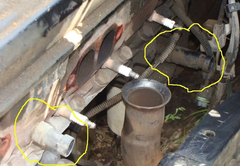 Here are the truck senders: 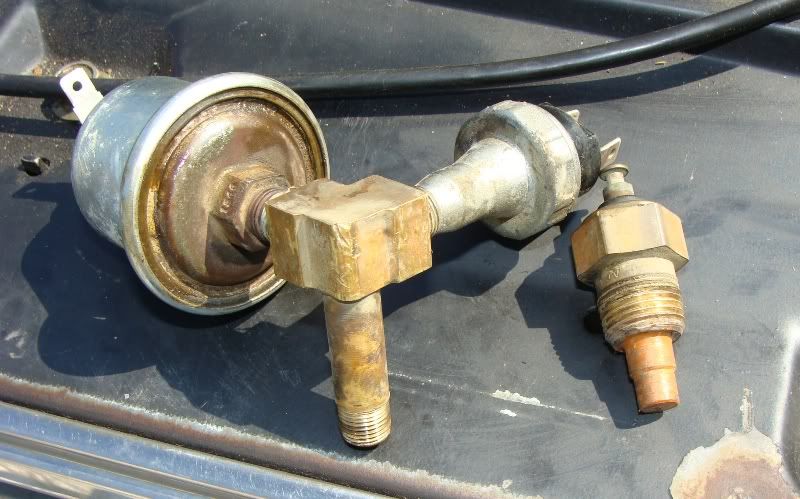 I also notice there are some electical components I don't know what are? I know one of these is a fuel pump relay....so what are the other pieces? do I need them? 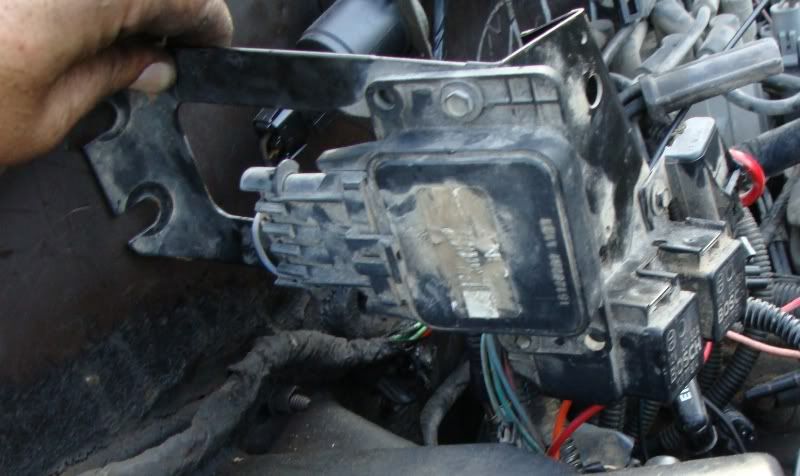
|

|

|
|
08-25-2009, 01:16 AM
|
#27 |
|
Registered User
Join Date: Oct 2003
Location: OC CA
Posts: 1,374
|
Re: 5.7 TBI in an 86????? Anyone done this swap??
Mike
First photo. The T combo. One of the two sensors is a pressure transducer which is used for oil pressure gauge while the other is an oil pressure switch which is used for idiot light. Take a close look at both - look for GM part numbers. The temp sensor on the right should be screwed into the driver side cylinder head. Remove car sensor and replace with truck version. IMHO, now is the time to get replacement sender as old ones can develop a leak. Second photo Combo bracket - this bracket was mounted on a passenger side fender skirt (B- Body) and is used to support ESC module, ?, couple AC circuit relays and ECM fuse holder. Electronic spark control (ESC) module is used in conjunction with knock sensor (KS) to provides a voltage signal to ECM when engine knock is detected. ESC module is analog signal conditioner - filter. Depending on severity of detected knock it will pulse 9 volt output to ECM, indicating presence and persistence of engine knock. //RF
__________________
"The Beast" 1975 Chevrolet C20 longbed 350/700R4! with 3inch body lift Dual Flowmasters Super 40's! TBI retrofit completed (2007-07-29)  New 383CID (+030) 08-304-8 9.5:1CR x36,005 (2012-12-17) |
|
|
|
|
08-25-2009, 10:29 PM
|
#28 |
|
Still Learning
Join Date: Jul 2009
Location: Central Oklahoma
Posts: 10,108
|
Re: 5.7 TBI in an 86????? Anyone done this swap??
RF,
You mentioned that one of the relays is for the A/C controls? Is this to kick the compressor on? I assume I will need to tie this into the truck harness? Another thing came up today that for some reason I never noticed. This transmission has an electrical speed sensor and the truck has a mechanical cable that runs the speedo. Is there a simple solution for this? Or let me rephrase, is there a cheap solution to get the speedo to run? We made good progress today on the install. Finished the exhaust, changed out the sending units, moved the tranny cross member, put the new straps on the rear U-joint. It looks like I will need to drill some holes for the cross member. 2 bolts on each side lined up. Also, the driveshaft seems to be just about the right length. Hopefully, we can wrap up all the mechanical this week and get to wiring this weekend. This is slow going when you only have an hour here and 2 hours there. Here are some pics: 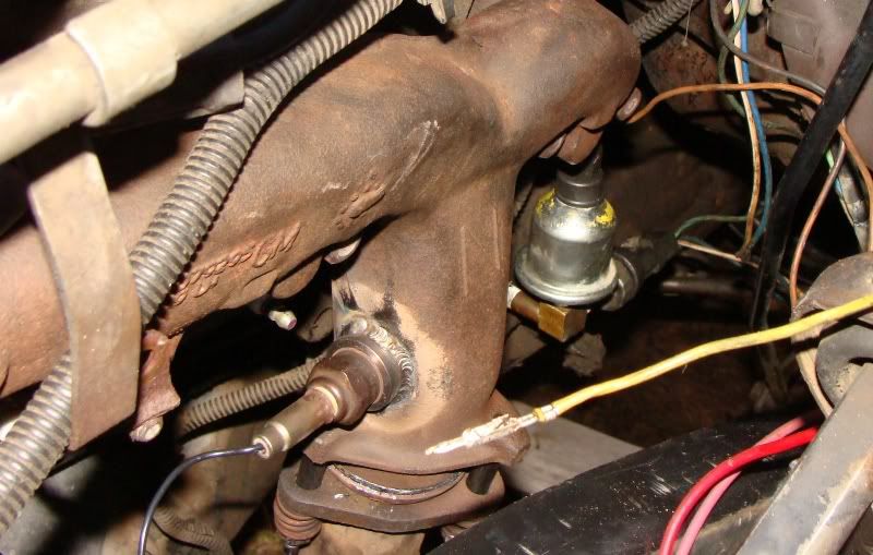 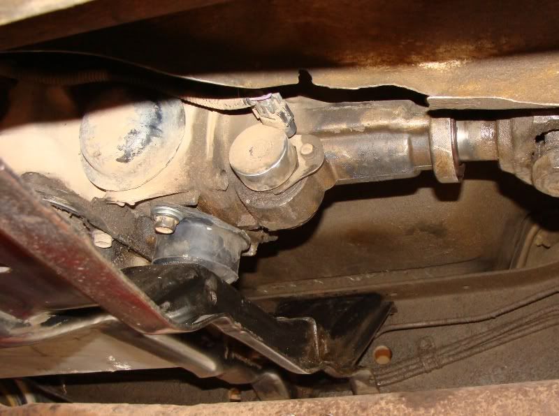 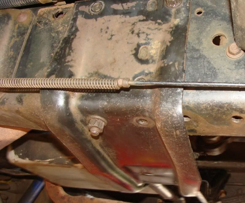 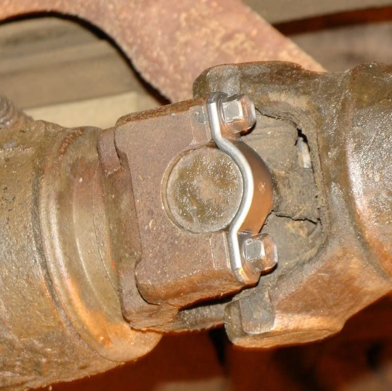
|
|
|
|
|
08-26-2009, 01:22 AM
|
#29 | |
|
Registered User
Join Date: Oct 2003
Location: OC CA
Posts: 1,374
|
Re: 5.7 TBI in an 86????? Anyone done this swap??
Quote:
Regarding AC control relays and circuit. AC control circuit will require some rework. I have a FSM for '91 B-body which covers AC circuit in detail. I do not have the same manual for your truck! If you can get your truck information than we have a good chance of putting a combo harness that will work. Regarding speedometer. Bad news - money involved. To get a fully functional spedo - VSS will require procurement of two parts. You have to get a mechanical speedometer driven gear housing - that's what plugs into transmission in place of your electronic vehicle speed sensor (VSS) from an earlier 700R4 equipped car or truck from JY or a local tranny shop. Try to get aluminum one - they last longer. Depending on tire/rear end ratio you'll have to change driven gear to get speedometer to read correct speed. Furthermore, to keep ECM happy an inline bolt-in VSS from JTR will have to be procured. TBI equipped cars and trucks used two-pulse (2000 pulses per mile) square wave VSS (it's a reed switch) through 1992. You can read a full explanation here: http://www.jtrpublishing.com/Pages/S...eedometer.html A lower cost VSS is available from Summit made Rostra Precision Controls 250-4153 http://www.summitracing.com/parts/RPC-250-4153/ Specs for this part - number of pulses per revolution are not available. I did not use this part before so I have no first hand experience. Perhaps, worth a call to summit tech line. Another rely cheap inline VSS is made by SCS/Frigette 208-3606 - again no first hand experience with this one. More discussion with VSS retrofitting can be found here: http://www.binderplanet.com/forums/s...ad.php?t=50649 //RF
__________________
"The Beast" 1975 Chevrolet C20 longbed 350/700R4! with 3inch body lift Dual Flowmasters Super 40's! TBI retrofit completed (2007-07-29) New 383CID (+030) 08-304-8 9.5:1CR x36,005 (2012-12-17) |
|
|
|
|
|
08-26-2009, 08:55 AM
|
#30 | |
|
Still Learning
Join Date: Jul 2009
Location: Central Oklahoma
Posts: 10,108
|
Re: 5.7 TBI in an 86????? Anyone done this swap??
Quote:
I am wondering if I tie truck A/C control wire(s) into the circuit that goes to the ecm for the a/c would that then control the relay to fire the a/c? What info about the truck is required to construct the harness you are talking about? Do you do this type of work? I am assuming you are a EE....is it just a hobby? Regarding the VSS, it looks like this with the proper gear ratio and tire size would be a direct replacement: 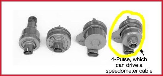 It is pretty pricey at a $101 plus the shipping. I wonder if any of the early 90s burb or blazer instrument panel with necessary wiring would solve the speedo issue? As always, thanks for the help! Mike |
|
|
|
|
|
08-26-2009, 12:01 PM
|
#31 | |
|
Still Learning
Join Date: Jul 2009
Location: Central Oklahoma
Posts: 10,108
|
Re: 5.7 TBI in an 86????? Anyone done this swap??
Quote:
I tried to use the high pressure power steering line from the truck it would not mount up to the car engine. (not because of fittings more because of wrong routing) I'm wondering if I need to get a hose that will fit say a 90-92 burb or blazer? |
|
|
|
|
|
08-26-2009, 12:27 PM
|
#32 |
|
Senior Member
Join Date: Apr 2000
Location: Delta,Pa
Posts: 14,950
|
Re: 5.7 TBI in an 86????? Anyone done this swap??
you could try to bend the line to make it fit. if you bend it slowly and your careful not to crack or kink the line you can probably move it enough to make it work for ya. the other option is to have a hose made. you would take the truck hose for the steering box side and the car hose for the pump side and have them use each end and make u a new hose.
__________________
Owner of North Point Car Care in Dundalk Md. We specialize in custom exhaust on both modern and classic vehicles. We are a full service auto shop from classics to modern vehicles. Feel free to contact me with questions. I will give a 10% discount to any board member. |
|
|
|
|
08-26-2009, 12:51 PM
|
#33 | |
|
Still Learning
Join Date: Jul 2009
Location: Central Oklahoma
Posts: 10,108
|
Re: 5.7 TBI in an 86????? Anyone done this swap??
Quote:
I tried bending it to fit. It still needs a lot more than I could get out of it. I call local autozone I'm hoping the hose for a 90-92 suburban will be a direct replacement. I will let you know. Thanks, Mike |
|
|
|
|
|
08-26-2009, 07:30 PM
|
#34 |
|
BAD BOW-Silverado XST
Join Date: May 2000
Location: Senior Member from Austin, TX
Posts: 6,431
|
Re: 5.7 TBI in an 86????? Anyone done this swap??
Here is great article on a TBI swap.
http://users.sfo.com/~eagle/howell.html |
|
|
|
|
08-27-2009, 09:32 AM
|
#35 | |
|
Registered User
Join Date: Oct 2003
Location: OC CA
Posts: 1,374
|
Re: 5.7 TBI in an 86????? Anyone done this swap??
Quote:
The four pulse unit will not work very well with your car ECM. Assuming that 4 pulse VSS is a square pulse (On-OFF vs. AC) type will cause ECM to detect twice the actual speed and depending on ECM calibration fuel cut off will occur at much lower actual speed (around 55 MPH vs. 110 MPH). Not good. Early 90's trucks & SUVs used the electronic vehicle speed sensor and DRAC module for electronic speedometer. That system is a kludgee mess as DRAC provided different frequency pulse signal to various sub systems (ECM, Spedo, Anti-lock brake computer). This simplest solution is to get 2000ppm inline VSS and non electronic speedometer gear housing. Yes, I am EE - non automotive, but I have a lot of respect for auto boys since their environmental requirements exceed industrial ratings and probably on the par with mil specs. AC wiring requires a bit of combining of truck controls with your new ECM. //RF
__________________
"The Beast" 1975 Chevrolet C20 longbed 350/700R4! with 3inch body lift Dual Flowmasters Super 40's! TBI retrofit completed (2007-07-29) New 383CID (+030) 08-304-8 9.5:1CR x36,005 (2012-12-17) |
|
|
|
|
|
08-27-2009, 11:28 AM
|
#36 |
|
Still Learning
Join Date: Jul 2009
Location: Central Oklahoma
Posts: 10,108
|
Re: 5.7 TBI in an 86????? Anyone done this swap??
RF,
What would you suggest doing with the vss? I guess I need to get the aluminum housing you spoke of and the inline electronic vss? Any idea what part numbers? thanks, Mike |
|
|
|
|
08-27-2009, 07:47 PM
|
#37 | |
|
Registered User
Join Date: Oct 2003
Location: OC CA
Posts: 1,374
|
Re: 5.7 TBI in an 86????? Anyone done this swap??
Quote:
You'll need the following: Speedometer Driven Gear (43) Speedometer Housing & Support Bracket (44) Speedometer Housing O-Ring (42) http://www.tcsproducts.com/images/st..._schematic.pdf All three items can be sourced from JY. The only catch is get a correct driven gear that gets speedometer cable to turn at 1000 tire revs/mile - this is straight forward and several handy references are availlable. The following links are will provide you with a good reference information: Look for part # 54 (P) http://www.partshp.com/speedometer_gears.htm and http://www.73-87.com/7387garage/drivetrain/speedo.htm VSS I think I covered this subject extensively in prior posting. Attached photos capture my setup - I run this my conversion. That yellow module is a JTR 2000PPM TBI VSS bolted to speedometer housing and speedometer cable is bolted into VSS output. Photos were taken at an awkward angle - sorry. //RF
__________________
"The Beast" 1975 Chevrolet C20 longbed 350/700R4! with 3inch body lift Dual Flowmasters Super 40's! TBI retrofit completed (2007-07-29) New 383CID (+030) 08-304-8 9.5:1CR x36,005 (2012-12-17) |
|
|
|
|
|
08-30-2009, 02:45 PM
|
#38 |
|
Still Learning
Join Date: Jul 2009
Location: Central Oklahoma
Posts: 10,108
|
Re: 5.7 TBI in an 86????? Anyone done this swap??
Which one of the senders is for "idiot" light and which one goes to the pressure gage?
|
|
|
|
|
08-30-2009, 11:11 PM
|
#39 |
|
Registered User
Join Date: Oct 2003
Location: OC CA
Posts: 1,374
|
Re: 5.7 TBI in an 86????? Anyone done this swap??
Mike
1) Fuel Pump relay wiring Fuel pump relay socket on a 91 B- Body should have the following wires: 1) black-white (16AWG) | coil ground 2) dark green-white (16AWG) | coil hot - pulled by ECM to +12 V to activate FP relay. 3) Orange (10AWG) (NO - 87)| Battery hot (there should be 20 Amp inline fuse) 4) Red (16AWG) (NC - 87a)| Fuel pump test (4" pig tail with a blade connector) 5) Gray (10AWG) (COM - 30)| Switched Fuel Pump line - this should be connected to FP + terminal. 2) Ignition On Power I end up wiring a simple relay circuit (see Painless Wiring switched fuse box #70107 for electrically challenged) that gets energized when ignition is on or in start position. For this you'll have to probe your fuse box and find a spare tap port (there should be several ) that remain hot when ignition key is in run and start. This is very important to make sure that this port STAYS hot during cranking!!! Otherwise your ECM will never get a chance to fire injectors during cranking.  3) AC control circuit Will have to dig into it since B-Body ECM compensates idle RPM when AC is commended to ON. It makes for better idling setup. //RF
__________________
"The Beast" 1975 Chevrolet C20 longbed 350/700R4! with 3inch body lift Dual Flowmasters Super 40's! TBI retrofit completed (2007-07-29) New 383CID (+030) 08-304-8 9.5:1CR x36,005 (2012-12-17) Last edited by rfmaster; 08-30-2009 at 11:25 PM. |
|
|
|
|
08-30-2009, 11:32 PM
|
#40 | |
|
Still Learning
Join Date: Jul 2009
Location: Central Oklahoma
Posts: 10,108
|
Re: 5.7 TBI in an 86????? Anyone done this swap??
Quote:
While your on here, which one of the oil sending units was the one for the idiot light? I need to get rid of it and put the original one for the ecm back on there. right now, I am searching ebay to find some fuel line inline pump filter clamps etc. BTW, how did you tie into the tank? this truck has dual tanks and I assume there is a switching valve under there....so I guess that is where I cut the 5/16 line and tie into with the inline pump? |
|
|
|
|
|
09-08-2009, 11:30 AM
|
#41 |
|
Still Learning
Join Date: Jul 2009
Location: Central Oklahoma
Posts: 10,108
|
Re: 5.7 TBI in an 86????? Anyone done this swap??
Update:
I had a few hours to spare over the long weekend. I did a mock up of the wiring that will be perminant once I get this harness figured out. I hooked up everything I thought was necessary to make it run including the fuel tank and lines from the donor car. (with the tank sitting on the ground).I was able to get fuel to the TB but never made the injectors fire. I can pour gas in and it will run until it runs out. I was glad to hear it run but dissappointed I can't figure the injectors out. I looked all over CJ's thread and can't find what would cause this problem. Any suggestions? |
|
|
|
|
09-08-2009, 01:45 PM
|
#42 |
|
Senior Member
Join Date: Apr 2000
Location: Delta,Pa
Posts: 14,950
|
Re: 5.7 TBI in an 86????? Anyone done this swap??
the ignition module times the injector firing on these motors. theres also a fuse for the injectors showing as fuse #11 i cant save these wiring diagrams out of mitchell and send them to you. have you checked to make sure you have voltage to the injectors?
__________________
Owner of North Point Car Care in Dundalk Md. We specialize in custom exhaust on both modern and classic vehicles. We are a full service auto shop from classics to modern vehicles. Feel free to contact me with questions. I will give a 10% discount to any board member. |
|
|
|
|
09-08-2009, 01:50 PM
|
#43 | |
|
Still Learning
Join Date: Jul 2009
Location: Central Oklahoma
Posts: 10,108
|
Re: 5.7 TBI in an 86????? Anyone done this swap??
Quote:
|
|
|
|
|
|
09-08-2009, 01:51 PM
|
#44 |
|
Senior Member
Join Date: Apr 2000
Location: Delta,Pa
Posts: 14,950
|
Re: 5.7 TBI in an 86????? Anyone done this swap??
there should be a ride wire that runs to both injectors thats the power wire. one injector wire is dark blue the other dark green these are the trigger wires from the computer.
__________________
Owner of North Point Car Care in Dundalk Md. We specialize in custom exhaust on both modern and classic vehicles. We are a full service auto shop from classics to modern vehicles. Feel free to contact me with questions. I will give a 10% discount to any board member. |
|
|
|
|
09-08-2009, 02:40 PM
|
#45 | |
|
Still Learning
Join Date: Jul 2009
Location: Central Oklahoma
Posts: 10,108
|
Re: 5.7 TBI in an 86????? Anyone done this swap??
Quote:
I'm a little confused about the pink/black wire in your diagram? Where does it go? I have it tied into the power on during start and run from the fuse box terminal. You show it going to gauge/fuse? I feel like I don't have power hooked up on the ecm somewhere. I can hear the fuel pump relay kick on and pressure up the fuel system. But it won't squirt gas at the injectors. I think we need to see that we are getting power to them first and then go from there. Mike |
|
|
|
|
|
09-08-2009, 05:25 PM
|
#46 | |
|
Registered User
Join Date: Oct 2003
Location: OC CA
Posts: 1,374
|
Re: 5.7 TBI in an 86????? Anyone done this swap??
Quote:
Attached circuit diagram is my circuit implementation that I have built for my '75 conversion. The pink-black wire is used to power up auxiliary gauges (WBO, Tach, etc). You can omit it if not needed for your build. Since you can get engine to run by dumping fuel into TB it indicates that you have ignition, but ECM is not firing injectors. Two possibilities - ECM is not getting power during cranking or injectors do not get 12 volts during cranking. Got to run - will continue. //RF
__________________
"The Beast" 1975 Chevrolet C20 longbed 350/700R4! with 3inch body lift Dual Flowmasters Super 40's! TBI retrofit completed (2007-07-29) New 383CID (+030) 08-304-8 9.5:1CR x36,005 (2012-12-17) |
|
|
|
|
|
09-08-2009, 09:39 PM
|
#47 |
|
Still Learning
Join Date: Jul 2009
Location: Central Oklahoma
Posts: 10,108
|
Re: 5.7 TBI in an 86????? Anyone done this swap??
Thanks RF,
Your right I wasn't getting power to the injectors but I think I found the reason. One red wire from the donor I suspected needed hooked up while the key is on was unhooked. When I put power to it the injectors started squirting. It now kinda runs under it's own power (still has to be wired permanantly). I was trying to figure the fuel lines and I may be wrong but it sure looks like the original fuel line is 3/8" The return looks like 1/4". I guess I still need to run a 5/16 return? I picked some 3/8 steel line from Autozone and it is the same dia. as the original. Also there was a lot of discussion about the use of dual tanks. I don't understand why we can't just tie into the main line and use one pump? I guess if your driving down the road under a heavy load it may stumble the engine? Maybe a little? If it's unsafe then I may need to consider the small pump to move the fuel from one tank to the other. Things to do still: Finish the wiring Install the new fuel pump fix all the vacuum leaks change the starter? it sounds like the gear is hanging on the flexplate install speedo gear and vss make it driveable
__________________
Mike "69 Short Wide" My Project 86 Silverado Landen's Project Instagram: @mcbassin My Website C/10 Club Oklahoma Facebook Group Last edited by mcbassin; 09-08-2009 at 09:41 PM. |
|
|
|
|
09-09-2009, 01:43 AM
|
#48 | |
|
Registered User
Join Date: Oct 2003
Location: OC CA
Posts: 1,374
|
Re: 5.7 TBI in an 86????? Anyone done this swap??
Quote:
Looks like you are getting close to a working solution. Just be aware that you are dealing with 20+ year old OE wiring harness. Use of auxiliary relay block removes current from old harness (including ignition key) making the overall installation robust. It is extra work, but it provides long term reliability. On Fuel Lines I used both 3/8" lines for supply and return. You can go with 5/16" return, but why bother. Do not use 1/4" vapor line for fuel return line. The back pressure will screw up fuel pressure regulator in the TB. This will create fuel delivery havoc! On dual tanks I have fully functioning dual tank system. This system revivals the one found on B-737 - no kidding:  The fuel system took me about four month to fabricate (I was not in a hurry) which included a lot of 3/8" fuel line cutting and bending (soft steel). Tank select valves and low pressure lift pump: 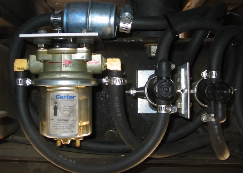 Low pressure pump lifts fuel out of selected main tank and feeds it into surge tank which provides un-interrupted fuel supply to high pressure EFI pump. Surge is needed since I have non baffled (pre EFI) main 20 G tanks: 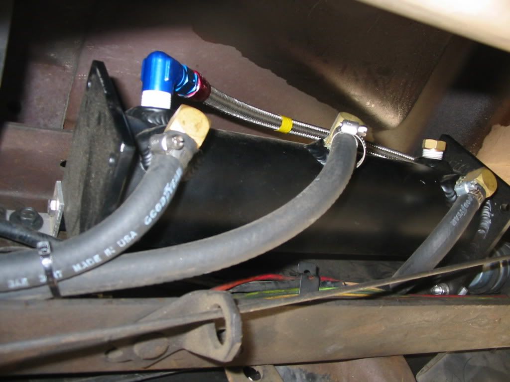 //RF
__________________
"The Beast" 1975 Chevrolet C20 longbed 350/700R4! with 3inch body lift Dual Flowmasters Super 40's! TBI retrofit completed (2007-07-29) New 383CID (+030) 08-304-8 9.5:1CR x36,005 (2012-12-17) |
|
|
|
|
|
09-09-2009, 08:02 AM
|
#49 |
|
Still Learning
Join Date: Jul 2009
Location: Central Oklahoma
Posts: 10,108
|
Re: 5.7 TBI in an 86????? Anyone done this swap??
I really like what you did with your fuel system! That is really nice! I could fab up a tank like that. I'm not sure we need to worry about the fuel supply since this will be a road only 2wd truck. I totally understand why you did yours like that. As far as the lines I am using, I am really thinking about using the original car fuel lines since they are the correct size and they have the correct fittings and have an inline filter setup already. I just have to make fittings to adapt to the truck lines or use the quick connect fittings from the tank.
On the power, I have thought about the relay setup. I want to build a setup like that and I'm sure with your diagram I can. Right now I'm wanting to get past the mess that I have of the harness. It really looks like a rat got under the hood. I need to have the best reliability possible (it will be driven by a kid). This project when done will move us toward finishing the 69 project we started. I would really like to install a 5.3 or 6.0 in it with matching late model tranny. thanks for all the help! Mike |
|
|
|
|
09-09-2009, 04:14 PM
|
#50 | |
|
Registered User
Join Date: Oct 2003
Location: OC CA
Posts: 1,374
|
Re: 5.7 TBI in an 86????? Anyone done this swap??
Quote:
Since you have car fuel lines available I would use them. Just be aware that any bends must be done with a tube bender to avoid collapsing (or worst restricting ) fuel lines. Tip on EFI harness routing. Just layout wiring in the engine compartment the best way you can and route all plugs to their respective locations. Take pictures and them play around on a kitchen table with a pencil hand sketch. This way you'll have a good idea how to route wire harness. Wire harness requires protection - hence invest in some 1/4, 3/8" and 1/2" split looms. For individual branches (single connector) I used 1/4" loom which can safely handle 1- 4 wires. When you have to use high temperature automotive grade electrical tape. DO NOT use commonly available hardware store electrical tape as it is not temperature rated for under hood operation. Professional electrical supply houses have this tape - it is a bit more, but it does not leave a black stinky mess. I had decent results using Scotch Supper 33+ electrical tape from 3M. It is rated for 105C (220F) continuous operation and resistant to oil, water and chemicals.
__________________
"The Beast" 1975 Chevrolet C20 longbed 350/700R4! with 3inch body lift Dual Flowmasters Super 40's! TBI retrofit completed (2007-07-29) New 383CID (+030) 08-304-8 9.5:1CR x36,005 (2012-12-17) |
|
|
|
|
 |
| Bookmarks |
|
|


 Linear Mode

