
|
 06-05-2009, 08:41 PM
|
#201 |
|
Registered User
Join Date: Jan 2007
Location: Lexington, TN
Posts: 1,427
|
Re: Tbi swap build thread
...
__________________
The fleet 94 Chevy 4x4 reg cab 2018 Traverse (wifes car) 1977 SWB stepside 1949 Chevy truck Last edited by cjracing15; 06-05-2009 at 08:45 PM. |

|

|
|
06-05-2009, 08:43 PM
|
#202 |
|
Registered User
Join Date: Jan 2007
Location: Lexington, TN
Posts: 1,427
|
Re: Tbi swap build thread
Ok then your fp is ok then. How did you make it run so that it filled the gas can? Also when you crank the engine over do you here a clicking noise from the injectors?
__________________
The fleet 94 Chevy 4x4 reg cab 2018 Traverse (wifes car) 1977 SWB stepside 1949 Chevy truck |
|
|
|
|
06-05-2009, 09:04 PM
|
#203 |
|
PROJECT 7DEUCE
 Join Date: Dec 2002
Location: GRANTS PASS OR
Posts: 21,589
|
Re: Tbi swap build thread
No clicking...... I did however find this wire unhooked any ideas on where it should go? It has power when the key is on??? Filled the gas can that im using for the return line while tring to start the truck....
__________________
GO BIG GREEN  GO DUCKS GO DUCKSMEMBER #6377 72 k-5 daily driver 6'' lift 35'' 350-350-205 slowly getting rust free. Project "7DEUCE" check out my build http://67-72chevytrucks.com/vboard/s...d.php?t=267665 Tim Powell..R.I.P EastSideLowlife..... R.I.P.. Last edited by FRENCHBLUE72; 06-05-2009 at 09:06 PM. |
|
|
|
|
06-06-2009, 02:08 AM
|
#204 |
|
Registered User
Join Date: Oct 2003
Location: OC CA
Posts: 1,374
|
Re: Tbi swap build thread
FrenchBlue72
Please Refer to figure below 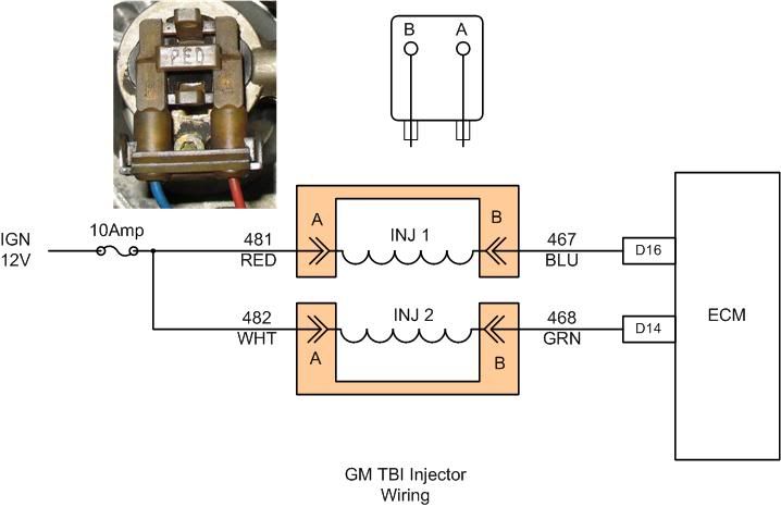 Background Information Basically, GM implemented a very simple TBI injector circuit. In this implementation ECM acts as a switch pulling Pin B of injector connector to ground completing the circuit energizing injector - fuel is delivered. Ignition switch supply is provided via two circuits 481, 482 (red and white wires) and are always on (as long as ignition key is in run or starting position). Checks Requires a functioning DVM - no excuses now, alright??? Injector coil 1) Everything is off, disconnect injector connectors from injectors by gently squeezing release tabs. Set DVM to measure resistance (Ohms), set to lowest range available <300 Ohms. Ignore this if you have a fancy auto ranging DVM. Measure resistance of each injector. Depending on your DVM and test lead resistance you should be able to measure individual coil resistance - about 1.1 to 1.5 Ohms for typical GM injector. If you are reading very high resistance - time to cry. If injectors check out then step 2. 2) Verify ignition voltage supply With both connectors disconnected make sure that they do not come into contact with anything in the engine compartment. Once secured, turn ignition into run position and measure voltage at Pin A off each connector. With a good battery you should see 11.5 to 12.0Vdc with respect to ground (bat negative terminal). If there is no voltage verify ignition fuse. 3) Re-install injector connectors if step 2 is good. With ignition on, engine stopped both Pin A & B should measure 11.5 to 12.0 with respect to ground. If Pin B fails to measure same voltage as Pin A then it is possible that connector is making a good contact with injector pins or there is an open injector winding when connector is installed on injector. 4) ECM PWM verification (this requires NOID or un-powered 12 volt test light) For this test DVM a typical DVM response time is to slow (there are units that can measure frequency or pulses specifically for PWM circuit troubleshooting) and a simple un-powered 12 volt test light will do the trick. Connect ground lead to engine ground and probe Pins A & B of each injector connector - light should be one for both as long as ignition is on, engine stopped. Get a helper to crank engine while probing Pin B of each connector - the light should be blinking off periodically. This is normal. Otherwise, if it remains solid that may indicate that ECM is not pulling injector circuit 467, 468 to ground. This may be caused by brake in harness, bad injector pull down circuit, etc. Manual shorting of injector control circuit - Pin B is not recommended, but this can only be done once supply voltage pind has been verified (red/white) and only for a short time. //RF
__________________
"The Beast" 1975 Chevrolet C20 longbed 350/700R4! with 3inch body lift Dual Flowmasters Super 40's! TBI retrofit completed (2007-07-29) New 383CID (+030) 08-304-8 9.5:1CR x36,005 (2012-12-17) |
|
|
|
|
06-06-2009, 08:11 AM
|
#205 |
|
Registered User
Join Date: May 2009
Location: Space City! (TX)
Posts: 46
|
Re: Tbi swap build thread
RF - thanks for the latest diagram. I now realize that the your statement about "both pins measuring 12V" that I originally disagreed with was because you were measuring the voltage with the connector attached to the injector. I normally disconnect things since it can be tough to get a probe on the terminals when connected - I assumed (the old ass out of you and me adage is correct in this instance) you were probing the connector when disconnected, which would show only 12V on the red or white wires of the terminals and an open circuit across the connector terminals like I stated. So, in retrospect, your statements are correct when measuring with everything connected and mine are also correct when disconnected. BTW - all your diagrams do ROCK!
cjracing: You are correct that that the ECM requires both a starter signal and oil pressure signal to fire the injectors, however, my understanding is that the oil pressure signal is not required when starting/cranking. That is, when cranking in START, the ECM sees the signal from the starter and doesn't look at the oil pressure as it realizes that the engine's oil pressure may not have built to a sufficient pressure as yet. Once started and in RUN, the ECM requires oil pressure to continue to fire. However, getting back to the start sequence, the ignition module signal to show the engine is spinning is also required by the ECM before firing the injectors. That is, if the ECM were to fire the injectors and the engine wasn't spinning, there would be a bunch of gas being introduced into the TB and manifold that could ignite out of the firing sequence - bad news. In summary, in START, the ECM requires the starter signal to tell it to ignore the oil pressure, but also requires an ignition module signal to tell it the engine is spinning before firing the injectors. In RUN, the ECM requires both the oil pressure and ignition module signals before firing the injectors. Hopefully this is now clear (as mud, I'm sure). Mark |
|
|
|
|
06-06-2009, 09:07 AM
|
#206 | |
|
Registered User
Join Date: Oct 2003
Location: OC CA
Posts: 1,374
|
Re: Tbi swap build thread
Quote:
1227747 ECM uses starter motor (aka cranking) signal and DRP signal from dizzy to enable start up sequence, which includes enrichment sequence if CTS indicate cold coolant temperature. Now, the oil pressure signal is really a fuel pump voltage monitor. In these early EFI systems GM put a primitive back to keep fuel pump operating by installing (normally open - NO) oil pressure switch in parrallel with FP relay contacts. If FP relay fails, but as long as oil pressure is above 4-6 PSI the oil pressure switch will keep current flowing to the fuel pump. FP relay (kinda) gets tested during POST sequence - ignition key off - on. SES light will go from on - off - steady on if all is well until engine starts. During POST ECM will try to power FP for about 2 seconds and shuts off. However, ECM monitors the FP relay switched side voltage when DRP are present and will set Code 54 if the voltage is low. Official description------------> Powertrain Controls - ECM/PCM Code 54 Fuel Pump Circuit CODE 54 - FUEL PUMP CIRCUIT (LOW VOLTAGE) CIRCUIT DESCRIPTION : The status of the fuel pump CKT 120 is monitored by the ECM at terminal "B2" and is used to compensate fuel delivery based on system voltage. This signal is also used to store a code if the fuel pump relay is defective or fuel pump voltage is lost while the engine is running. There should be about 12 volts on CKT 120 for at least 2 seconds after the ignition is turned, or any time reference pulses are being received by the ECM. Code 54 will set if the voltage at terminal "B2" is less than 2 volts for 1.5 seconds since the last reference pulse was received. This code is designed to detect a faulty relay, causing extended crank time, and the code will help the diagnosis of an engine that "Cranks But Will Not Run." If a fault is detected during start-up, the "SERVICE ENGINE SOON" light will stay "ON" until the ignition is cycled "OFF". //RF
__________________
"The Beast" 1975 Chevrolet C20 longbed 350/700R4! with 3inch body lift Dual Flowmasters Super 40's! TBI retrofit completed (2007-07-29) New 383CID (+030) 08-304-8 9.5:1CR x36,005 (2012-12-17) |
|
|
|
|
|
06-06-2009, 04:08 PM
|
#207 | |
|
Registered User
Join Date: May 2009
Location: Space City! (TX)
Posts: 46
|
Re: Tbi swap build thread
Quote:
FB72: that connector appears to be the EAC (electric air control) solenoid wire connector, which controls the air pump diverter valve. If you aren't running an air pump, no big deal - it can be left unconnected. I say it "appears to be the EAC" since the connector in your picture looks exactly like the one on my '87 TBI harness (which has an operable air pump and diverter valve), however, your tan or yellow wire is not the same as my pink w/ black stripe wire - the color differences could be due to different model year harnesses. The yellow or tan wire (or pink/black in my case) should be the one with 12V+ with respect to ground when ignition is on (for clarity - I'm talking about probing the connector when removed). The brown wire is the same color as mine and you can confirm this is the EAC wire by checking continuity between the brown wire and terminal C2 on the smaller (24 pin, not 32 pin) of the two ECM connectors. Good luck. Mark |
|
|
|
|
|
06-06-2009, 05:05 PM
|
#208 | |
|
Registered User
Join Date: May 2009
Location: Space City! (TX)
Posts: 46
|
Re: Tbi swap build thread
Quote:
Mark |
|
|
|
|
|
06-06-2009, 05:26 PM
|
#209 |
|
Registered User
Join Date: May 2009
Location: Space City! (TX)
Posts: 46
|
Re: Tbi swap build thread
FB72: I made a mistake... terminal C2 is on the larger of the two ECM connectors (32 pin, not 24) - sorry.
|
|
|
|
|
06-06-2009, 07:35 PM
|
#210 |
|
PROJECT 7DEUCE
Join Date: Dec 2002
Location: GRANTS PASS OR
Posts: 21,589
|
Re: Tbi swap build thread
Well guys I just got off work im gonna roll the truck into the shop and lock myself in there..... Thinking cap....check....test light ...check....volt meter....check.... no kids check....yep good to go..
__________________
GO BIG GREEN GO DUCKSMEMBER #6377 72 k-5 daily driver 6'' lift 35'' 350-350-205 slowly getting rust free. Project "7DEUCE" check out my build http://67-72chevytrucks.com/vboard/s...d.php?t=267665 Tim Powell..R.I.P EastSideLowlife..... R.I.P.. |
|
|
|
|
06-06-2009, 08:43 PM
|
#211 |
|
PROJECT 7DEUCE
Join Date: Dec 2002
Location: GRANTS PASS OR
Posts: 21,589
|
Re: Tbi swap build thread
Step one...... If I fail it why should I cry????
__________________
GO BIG GREEN GO DUCKSMEMBER #6377 72 k-5 daily driver 6'' lift 35'' 350-350-205 slowly getting rust free. Project "7DEUCE" check out my build http://67-72chevytrucks.com/vboard/s...d.php?t=267665 Tim Powell..R.I.P EastSideLowlife..... R.I.P.. |
|
|
|
|
06-06-2009, 08:59 PM
|
#212 | |
|
Registered User
Join Date: Oct 2003
Location: OC CA
Posts: 1,374
|
Re: Tbi swap build thread
Quote:
//RF
__________________
"The Beast" 1975 Chevrolet C20 longbed 350/700R4! with 3inch body lift Dual Flowmasters Super 40's! TBI retrofit completed (2007-07-29) New 383CID (+030) 08-304-8 9.5:1CR x36,005 (2012-12-17) |
|
|
|
|
|
06-06-2009, 10:07 PM
|
#213 |
|
Registered User
Join Date: Apr 2009
Location: Arvada, Colorado
Posts: 84
|
Re: Tbi swap build thread
Hello All,
Sorry it has been soooo long. I have been realy busy with work. I did have some time to go to the local yards and find a 25 gallon gas tank for my TBI swap. I also found some of the relays off a Caddy that RF was talking about. I had a question about the relays RF: How do I know what wire of the bottom corelates to the number on the top. EX: relay #85 is the 12 gauge solid red wire, or the 12 gauge purple and black wire? I am using the relay for a 4 wire O2 sensor. I beleive I read in the post that you used and adapter plate to mate a TBI to an older manifold. This could save me a lot of time and work. Did you like the adapter plate, or would you modify the stock manifold to fit the older heads? Thanks again for all you help guys and good to see new posts .
|
|
|
|
|
06-06-2009, 10:11 PM
|
#214 |
|
PROJECT 7DEUCE
Join Date: Dec 2002
Location: GRANTS PASS OR
Posts: 21,589
|
Re: Tbi swap build thread
OK guys came in for dinner figured id give an update.... are ya ready... here it is........... I got fuel out of the injectors and they are clicking this is how ever when I ground them out I now have a good friend over who has messed with these so he has been a tremendous help as have you guys.... I have made little progress but at least I have made some.....
__________________
GO BIG GREEN GO DUCKSMEMBER #6377 72 k-5 daily driver 6'' lift 35'' 350-350-205 slowly getting rust free. Project "7DEUCE" check out my build http://67-72chevytrucks.com/vboard/s...d.php?t=267665 Tim Powell..R.I.P EastSideLowlife..... R.I.P.. |
|
|
|
|
06-06-2009, 10:25 PM
|
#215 |
|
Registered User
Join Date: Apr 2009
Location: Arvada, Colorado
Posts: 84
|
Re: Tbi swap build thread
Is this the correct o2 sensor? Only $29.00??? Junk? Found it here. http://www.car-stuff.com/carparts/gm...4000334534.htm Last edited by pancake; 06-06-2009 at 10:27 PM. |
|
|
|
|
06-06-2009, 11:59 PM
|
#216 |
|
PROJECT 7DEUCE
Join Date: Dec 2002
Location: GRANTS PASS OR
Posts: 21,589
|
Re: Tbi swap build thread
Well I have got to tell ya guys tonight was great........ Got the motor to run on its own whoooo hoooo.... I did however have to run a jumper wire from the battery to the batt lug on the alternator.. My ecm is not getting power to the orange wire on the gray side of the harness... So it looks like I must have missed a main power wire somewhere or I hooked up the ignition switch wrong? The truck runs but surges while idling but at this point I don't care I'm so happy to hear it run...... Thank you guys all of you I could not have done it with out the info gained from this thread...... Cj thanks for starting it...
__________________
GO BIG GREEN GO DUCKSMEMBER #6377 72 k-5 daily driver 6'' lift 35'' 350-350-205 slowly getting rust free. Project "7DEUCE" check out my build http://67-72chevytrucks.com/vboard/s...d.php?t=267665 Tim Powell..R.I.P EastSideLowlife..... R.I.P.. |
|
|
|
|
06-07-2009, 12:45 AM
|
#217 | |
|
Registered User
Join Date: Oct 2003
Location: OC CA
Posts: 1,374
|
Re: Tbi swap build thread
Quote:
On JY relays you'll have to get very friendly with a DVM, but most BOSCH style SPDT relays follow the numbering sequence: PIN 85 Coil (usually negative or ground connection) PIN 86 Coil (usually positive connection) PIN 30 Common pin PIN 87 Normally Open (NO) PIN 87A Normally Closed (NC) With a socket it is a bit of work, but coil wires almost always use smaller gauge wires - e.g. 16 AWG pink/black for +12 source and any color for a control switched circuit. For power relay contact look for large gauge wire - for example 10AWG red or orange color wire. You can (blindly) determine which wires lead to relay coil pins with a DVM - any pair of wires that you can measure 70-100 Ohms is your coil circuit wires. To verify relay contacts you can always power up relay with a 12V source while having DVM measuring the three power wires. But first you can find NC pair, then power up relay. It is basic electricity checking - sorry if I went to basic I just do not know what your comfort level is. On a manifold Q I went to a TBI specific manifold, but you can use adapter plate. I am currently looking to build 383 with Vortec (L31) heads using early 70's block I got from my colleague. I am looking into using Weind 8121 with 4150 adapter plate for TBI. I am guessing that you have ubiquitous Q-Jet intake - Transadapt makes a series of adapter for Q-Jet intakes. Look for a rear #2206 mounted plate as this will move TB bores over the larger secondaries and keep throttle cable length close to stock. You still may have to experiment with rear cable bracket - I had to that because of 1" spacer I used. //RF
__________________
"The Beast" 1975 Chevrolet C20 longbed 350/700R4! with 3inch body lift Dual Flowmasters Super 40's! TBI retrofit completed (2007-07-29) New 383CID (+030) 08-304-8 9.5:1CR x36,005 (2012-12-17) |
|
|
|
|
|
06-07-2009, 01:20 AM
|
#218 | |
|
Registered User
Join Date: Oct 2003
Location: OC CA
Posts: 1,374
|
Re: Tbi swap build thread
Quote:
USOS-4000 4 wire NBO I do not know - listing comes back to generic O2 heated unit covering many different models and makes. My guess this is a classic low cost generic replacement unit. It may work, but it will not be optimum since GM ECM close loop algorithms were optimized for Delco O2 sensors. Still, it should work - it just might not be optimum. Caveat Emperor! //RF
__________________
"The Beast" 1975 Chevrolet C20 longbed 350/700R4! with 3inch body lift Dual Flowmasters Super 40's! TBI retrofit completed (2007-07-29) New 383CID (+030) 08-304-8 9.5:1CR x36,005 (2012-12-17) |
|
|
|
|
|
06-07-2009, 02:28 AM
|
#219 |
|
Registered User
Join Date: Oct 2003
Location: OC CA
Posts: 1,374
|
Re: Tbi swap build thread
BOSCH relay with contact labels on its side
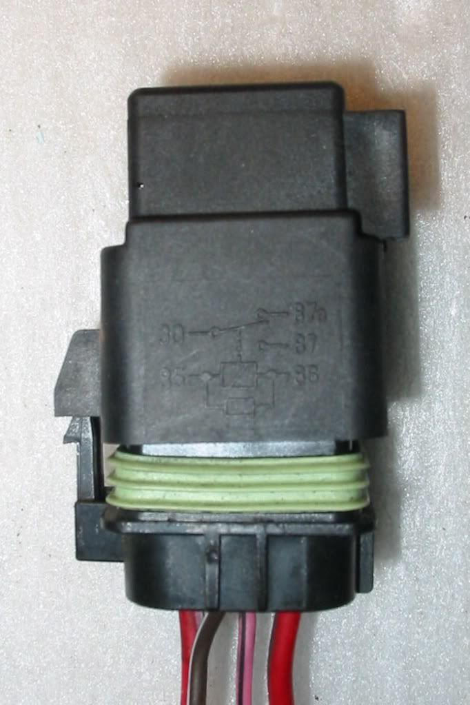 This one only uses NO contacts for SPST function. This is my relay stack (old photo - taken during summer of 07) 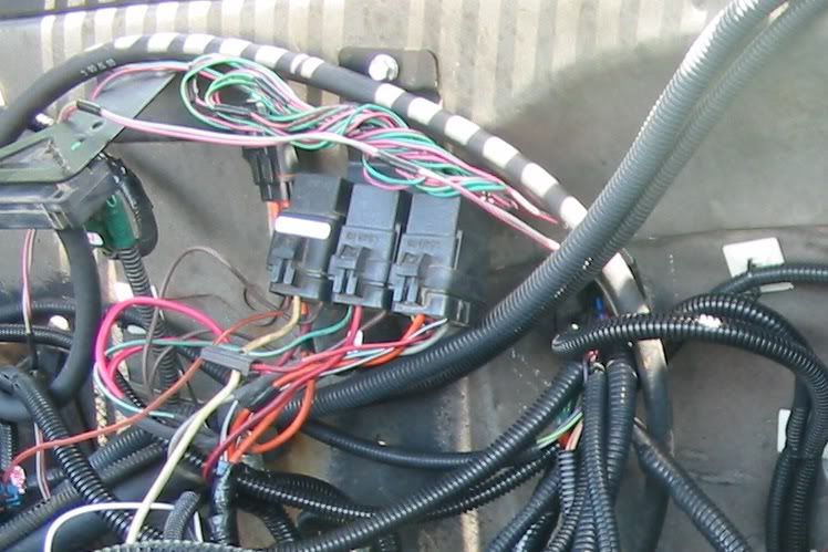 Left to right O2 heater relay, Fuel pump 2, Fuel Pump 1 - bracket of my favorite electrical donor - 4100 Cady! //RF
__________________
"The Beast" 1975 Chevrolet C20 longbed 350/700R4! with 3inch body lift Dual Flowmasters Super 40's! TBI retrofit completed (2007-07-29) New 383CID (+030) 08-304-8 9.5:1CR x36,005 (2012-12-17) |
|
|
|
|
06-07-2009, 06:35 AM
|
#220 | |
|
Registered User
Join Date: Jan 2007
Location: Lexington, TN
Posts: 1,427
|
Re: Tbi swap build thread
Quote:
Again great to see you got it running and, you are welcome about starting the thread. It has turned out to be just what I wanted, a place where you can get some answers on this swap.
__________________
The fleet 94 Chevy 4x4 reg cab 2018 Traverse (wifes car) 1977 SWB stepside 1949 Chevy truck |
|
|
|
|
|
06-07-2009, 09:20 AM
|
#221 | |
|
Registered User
Join Date: May 2009
Location: Space City! (TX)
Posts: 46
|
Re: Tbi swap build thread
Quote:
To modify the stock manifold, the two center holes on both sides of the manifold need to be oval-ized to allow the different bolt angle to line up with the holes in the heads. I tried using a cutter in a die grinder to enlarge the holes, but the cutter I was using quickly loaded up with aluminum and was worthless. I didn't have any other suitable cutters for the die grinder, so I used a coarse rat-tail file and filed the oval holes by hand (15-20 minutes per hole - phew!). Second, you need to compensate for the different bolt angle and how the four center bolt heads seat against the manifold. The shims you showed in Post #172 will work - that is what I used on the passenger side. On the driver's side, I could have also used the shims, but instead used a 4-1/2" cut-off wheel in my grinder and carefully changed the angle of the manifold so that the center bolt heads would seat flush. |
|
|
|
|
|
06-07-2009, 01:42 PM
|
#222 | |
|
Registered User
Join Date: Oct 2003
Location: OC CA
Posts: 1,374
|
Re: Tbi swap build thread
Quote:
TV cable geometry is critical - incorrect setup you can kiss your trany goodbye. I had to do some minor fabing (I used Holley 300-49 intake with 1" spacer). Throttle cable bracket came off some early 80's carbed car. Rear view 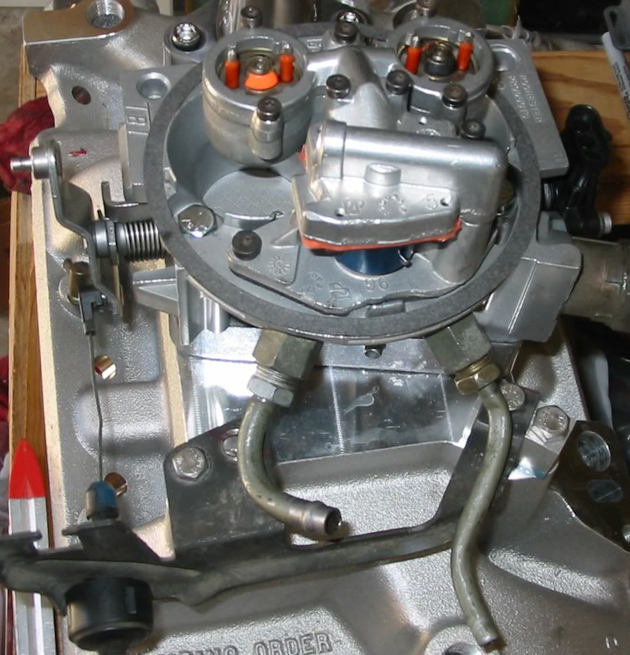 Driver side back 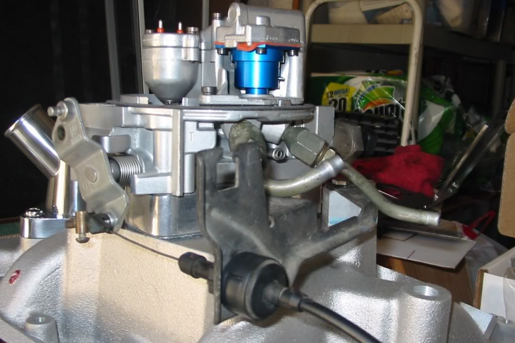 TV Cable side view  //RF
__________________
"The Beast" 1975 Chevrolet C20 longbed 350/700R4! with 3inch body lift Dual Flowmasters Super 40's! TBI retrofit completed (2007-07-29) New 383CID (+030) 08-304-8 9.5:1CR x36,005 (2012-12-17) |
|
|
|
|
|
06-07-2009, 10:30 PM
|
#223 |
|
Registered User
Join Date: Apr 2009
Location: Arvada, Colorado
Posts: 84
|
Re: Tbi swap build thread
Thanks RF for the pictures. I did pull the 3 relays off the strut tower on a cady. 2 are Bosch and 1 is ?.
Do have a part number for a AC Delco 4 wire 02 sensor? I will be getting an adaptor plate for the TBI and that should help with the install. The 31 gallon fuel tank was way to big for my 4x4 rig so I found a 25 gallon one from a 87 Blazer. Should work great. Will keep ypu all posted.
|
|
|
|
|
06-08-2009, 01:32 AM
|
#224 | |
|
Registered User
Join Date: Oct 2003
Location: OC CA
Posts: 1,374
|
Re: Tbi swap build thread
Quote:
4-Wire NBO part numbers AC Delco #: AFS75 GM #: 25312184 Delphi #: ES10006 //RF
__________________
"The Beast" 1975 Chevrolet C20 longbed 350/700R4! with 3inch body lift Dual Flowmasters Super 40's! TBI retrofit completed (2007-07-29) New 383CID (+030) 08-304-8 9.5:1CR x36,005 (2012-12-17) |
|
|
|
|
|
06-08-2009, 01:36 AM
|
#225 | |
|
Registered User
Join Date: Oct 2003
Location: OC CA
Posts: 1,374
|
Re: Tbi swap build thread
Quote:
Low fuel pressure Vacuum leak Bad MAP sensor Lastly - you need to reset IAC - it must be set to minimum air position. There is a procedure posted (use search) //RF
__________________
"The Beast" 1975 Chevrolet C20 longbed 350/700R4! with 3inch body lift Dual Flowmasters Super 40's! TBI retrofit completed (2007-07-29) New 383CID (+030) 08-304-8 9.5:1CR x36,005 (2012-12-17) |
|
|
|
|
 |
| Bookmarks |
| Thread Tools | |
| Display Modes | |
|
|


 Linear Mode

