
|
Register or Log In To remove these advertisements. |
|
|
|
|||||||
 |
|
|
Thread Tools | Display Modes |
 03-02-2013, 10:28 AM
|
#1 |
|
Registered User
Join Date: Jan 2010
Location: Forsyth, Ga
Posts: 1,012
|
67-72 non gauge dash bezel plug wiring diagram
Any one have this. Rewiring my bezel due to adding aftermarket gauges and want to make sure my printed circuit board reverse engineering is correct.
Posted via Mobile Device |

|

|
|
03-03-2013, 12:01 AM
|
#2 |
|
Msgt USAF Ret
  Join Date: Jan 2005
Location: Kalamazoo, Michigan
Posts: 8,703
|
Re: 67-72 non gauge dash bezel plug wiring diagram
Bill in order to avoid confusion I am going to reply in this thread because the other thread is pretty well solved and you will need more information than just how the idiot gauges are pinned regarding the circuit board.
The first point to make is that the circuit boards are too much different to be interchangable. However the cluster plugs are re-usable just by re-pinning the wires that locate in them. I believe the plugs are numbered by pin for wire location and each of them has 12 pin slots. The newer models have more than that but we will concern ourselves with the 67 to 72s. Here are the two types as posted by GMCPaul on his website which is in the forum FAQS. This is the idiot cluster with the charging light. Remember there are 12 pins in each plug with the corresponding wires. Here is the gauge connector wiring . Study the two diagrams closely and you can see that there are several differences between them and each one has wires not common to the other and each one has wires that are common but are in different locations. This is the plug, but you know that and you can see the pin numbers if you look closely. Now as I read you original post I am not clear on what it is that you want to do. My impression is that you want to keep the idiot light cluster and add the gauges that you want without changing the whole cluster and the circuit board. It is possible to do that but you will have to add the sensors and wiring for the added gauges. You will also have to figure some way to light the gauges unless they have internal bulbs and if they do then you can just tie into the gray wires on the idiot light cluster and ground the gauge bodies. It will be really simple to add the temperature oil and battery gauge and the volt gauge is easy too. If you're going to change to a complete gauge cluster from the idiot light cluster then you'll still have to change the sensors and re-pin the cluster plug. It's still not that hard.
__________________
VetteVet metallic green 67 stepside 74 corvette convertible 1965 Harley sportster 1995 Harley wide glide Growing old is hell, but it beats the alternative. Last edited by VetteVet; 03-03-2013 at 12:07 AM. |
|
|
|
|
03-03-2013, 02:13 AM
|
#3 |
|
Registered User
Join Date: Jan 2010
Location: Forsyth, Ga
Posts: 1,012
|
Re: 67-72 non gauge dash bezel plug wiring diagram
This what I have done
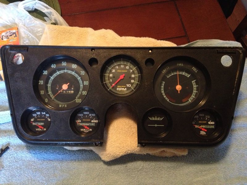 I kept the stock fuel and speedo and added the other gauges. So now I want to basically toss the circuit board and rewire. I was hoping to get the pin config to verify my reverse engineering of the circuit board. Thanks for that image from gmcpauls. I will check it against my findings. Posted via Mobile Device |
|
|
|
|
03-27-2013, 07:35 PM
|
#4 |
|
Registered User
Join Date: Feb 2013
Location: Mandan
Posts: 80
|
Re: 67-72 non gauge dash bezel plug wiring diagram
were did u get the gauges that fit in there did the come out of another truck
|
|
|
|
|
03-27-2013, 07:41 PM
|
#5 |
|
Registered User
Join Date: Jan 2010
Location: Forsyth, Ga
Posts: 1,012
|
Re: 67-72 non gauge dash bezel plug wiring diagram
They are autometer procomp gauges. The rpm gauge is 3 3/8" and the others are 2 5/8"
Posted via Mobile Device |
|
|
|
|
05-09-2013, 03:16 PM
|
#6 |
|
Registered User
Join Date: Oct 2012
Location: new orleans, la.
Posts: 217
|
did you do away with the printed board and wire direct to fues panel? looks great.
|
|
|
|
|
05-09-2013, 03:19 PM
|
#7 |
|
Registered User
Join Date: Jan 2010
Location: Forsyth, Ga
Posts: 1,012
|
Re: 67-72 non gauge dash bezel plug wiring diagram
Yes printed circuit board is gone. Replaced factory plug with a Doutche 12 pin and direct wired to that so I can disconnect easy if I ever need to remove cluster.
|
|
|
|
|
05-09-2013, 03:26 PM
|
#8 |
|
Registered User
Join Date: Oct 2012
Location: new orleans, la.
Posts: 217
|
Re: 67-72 non gauge dash bezel plug wiring diagram
thanks, starting to do mine, will sent a p[icture to ya when done, hope it comes out as good as yours, send youe em and some pictures of yours.
|
|
|
|
|
01-25-2016, 01:07 PM
|
#9 |
|
Registered User
Join Date: Jan 2016
Location: Taylorsville, UT
Posts: 1
|
Re: 67-72 non gauge dash bezel plug wiring diagram
I'm in the final stages of rewiring my 68 fleetside shortbed and (as per this thread) I need to provide the wires to the battery gauge. I see that plug positions 1 & 12 are the wires I need. My question is where do I connect to an internally regulated alternator?
I been reviewing lots of 67-72 chevy threads and have received lots of help - Thanks to all those that have shared! |
|
|
|
|
01-25-2016, 07:06 PM
|
#10 | |
|
Registered User
Join Date: Nov 2009
Location: Sherman, ME
Posts: 2,354
|
Re: 67-72 non gauge dash bezel plug wiring diagram
Quote:
The black wire on his diagram (the one that's connected to the junction block near the battery) should lead to pin #12 on the cluster connector. And the black wire with white stripe (that's connected to the power distribution splice) should lead to pin #1 on the cluster connector. Accidentally getting the #1 & #12 connections reversed won't do any harm but it will cause the battery gauge to read backwards (showing charge instead of discharge and vice versa). |
|
|
|
|
|
01-25-2016, 11:52 PM
|
#11 |
|
Msgt USAF Ret
Join Date: Jan 2005
Location: Kalamazoo, Michigan
Posts: 8,703
|
Re: 67-72 non gauge dash bezel plug wiring diagram
Here is how the original wiring is in the factory trucks. The ammeter wires are the ones with the circled fuses in them and the shunt is the red wire that runs from the battery fender junction to the alternator regulator junction in the harness.
With the alternator conversion, the external regulator wires are taken out of the harness so you may have to create a new junction for the alternator, SHUNT, cab power wire, and the new wire from the no. 2 wire for the alternator. This is the original wiring. Here is the clean version of the conversion. The original showing the external regulator. Notice the brown wire from the firewall and the red wire from the external regulator. The brown wire goes to the regulator at terminal 4 and the red wire goes from the regulator to the alternator, battery, cab wire, junction. The brown wire will become the no 1 wire to the internal regulated alternator and the red wire will come off the regulator and go to the no. 2 on the internal regulated alternator from the junction. And the clean conversion. Now we have the brown wire going from the firewall block to the no.1 on the alternator, and the red wire going from the no. 2 on the alternator, to the junction of the Large alternator wire, the battery power wire(SHUNT), and the cab power wire. The no. 1 ammeter wire goes here, and with a four amp fuse inline it runs all the way to the no. 1 pin cluster plug. The no. 12 wire goes from the battery junction on the right fender, with the fusible link and the other end of the battery (SHUNT) wire, again with a four amp fuse inline all the way to the no, 12 pin on the cluster plug. As an improvement, I recommend upgrading the large alternator wire to a 10 or even an 8 gauge wire because of the added output it is capable of.
__________________
VetteVet metallic green 67 stepside 74 corvette convertible 1965 Harley sportster 1995 Harley wide glide Growing old is hell, but it beats the alternative. |
|
|
|
|
04-11-2018, 10:35 AM
|
#12 |
|
Registered User
Join Date: Jun 2017
Location: Lebanon Ohio
Posts: 4
|
Re: 67-72 non gauge dash bezel plug wiring diagram
Anyone know where to purchase one of the plugs or the conductors that go into the plug? I'm missing two.
|
|
|
|
|
04-11-2018, 10:47 AM
|
#13 |
|
Registered User
Join Date: Oct 2012
Location: new orleans, la.
Posts: 217
|
Re: 67-72 non gauge dash bezel plug wiring diagram
been there on this one, make your own with male/female connectors,
|
|
|
|
|
04-11-2018, 03:24 PM
|
#14 | |
|
Registered User
Join Date: Nov 2009
Location: Sherman, ME
Posts: 2,354
|
Re: 67-72 non gauge dash bezel plug wiring diagram
Quote:
Another option would be to salvage some terminals from a donor vehicle. GM used this same style of instrument cluster connector in many cars & trucks from the late 60's up into the early 90's. If possible, try to match up the wire colors you need and cut them as long as possible from the donor vehicle. I don't recommend trying to un-crimp the terminals from the wires ... that's nearly impossible to do without damaging the terminal. |
|
|
|
|
|
| Bookmarks |
| Thread Tools | |
| Display Modes | |
|
|


 Linear Mode

