
 |
Register or Log In To remove these advertisements. |
|
|
|
|||||||
 |
|
|
Thread Tools | Display Modes |
|
|
#1 |
|
Registered User
Join Date: Oct 2016
Location: Ontonagon, MI
Posts: 56
|
Clutch linkage picture request
Hello,
I am looking for some good clutch linkage photos for a small block to help me work through some installation issues. I have a pile of parts that won't seem to fit together properly. I am particularly interested in these specific photos: 1) What does the upper push rod look like? How much bend does it have? 2) Where does the bellcrank ball stud connect to the engine block? 3) What does the connection between the lower push rod and clutch fork look like? My push rod has a shoulder on it that makes me assume that it passes through the fork. My transmission is from an 1984 and has no hole in the fork, only a dimple. 4) I know that there is a return or anti rattle spring in the system bit don't know where. A photo of that would also help. That you in advance. |
|
|

|
|
|
#2 |
|
Moderator
 Join Date: Jun 2017
Location: Cherryville, NC
Posts: 2,154
|
Re: Clutch linkage picture request
Hopefully the pics attached will give you an idea of layout,,,the pics are all of this board...the engine pivot ball srews into a threaded hole in the engine rear flange...if that hole is not threaded, you can buy aftermarket brackets to replace the hole...
There must also be a bracket on the chassis to support the other end of the cross shaft pivot....both ends of the cross shaft have bushings that must be in place...use lots of grease in there as most cross shafts dont have zerk fittings... The main rod from the cross shaft to the pedal only goes one way...if it upside down it wont fit in easily... Biggest issue I find is if the trans mount and or engine mounts are bad, the engine and trans will walk around when you push in the clutch pedal..make sure the mounts are in good shape..      
|
|
|

|
|
|
#3 |
|
The Older Generation
  Join Date: Aug 2006
Location: Montezuma, Iowa
Posts: 25,326
|
Re: Clutch linkage picture request
-
Here is a drawing to go with Aussie's pics. Only problem is it it for a right hand drive. (fitting I guess..  ..) All of the pieces would be the same though just on the opposite side of the truck.. Keep in mind there are 3 or 4 different engine ball mounting configurations.... This is on an I-6 ..) All of the pieces would be the same though just on the opposite side of the truck.. Keep in mind there are 3 or 4 different engine ball mounting configurations.... This is on an I-6LockDoc
__________________
Leon Locksmith, Specializing In Antique Trucks, Automobiles, & Motorcycles (My Dually Pickup Project Thread) http://67-72chevytrucks.com/vboard/s...d.php?t=829820 - |
|
|

|
|
|
#4 |
|
Moderator
 Join Date: Jun 2017
Location: Cherryville, NC
Posts: 2,154
|
Re: Clutch linkage picture request
One final thought, you havent mentioned if this is a 6 cyl to 350 conversion, as well as an auto to manual conversion.
There are several different engine mounting positions with these swaps, and each one will require a slightly different mix of parts. The critical things in this install to remember...the cross shaft must be a parallel to the ground as possible and the upper bell crank lever should be as close to 12 o'clock position when installed...maybe a little like 11.55 when viewed from the outside. When the clutch pedal is pushed down, the upper rod moves down against the bell crank cross shaft, the shaft rotates counter clock wise, pushing the lower bell crank lever backwards. The linkage pivot you mentioned has only a depression...you will need to use a round end push rod and retain it with a spring usually pulling back against the travel direction...these usually attach to the chassis near the pivot mount bracket. There are a multitude of after market kits available...if you need more help, just hollah...most of us dont mind helping out    
|
|
|

|
|
|
#5 | |
|
Registered User
Join Date: Oct 2016
Location: Ontonagon, MI
Posts: 56
|
Re: Clutch linkage picture request
Quote:
This is an auto to manual conversion, BBC to SBC (sort of). I purchased the truck last Fall and it came with a good running 454 and a slipping 700R4. While searching for a transmission, I came across an LT1/4L60E combo for a great price so I decided to go that route. As I started digging in, I decided that a true hot rod should have 3 pedals so I found myself a NP440. Out came the 454/700R4 and in went the LT1/NP440. I acquired a pedal set along with bellcrank and linkages from a 1968. I'm not sure but guessing that it was a L6 truck based on the way things are fitting up but not certain. When I tried to install the bellcrank the first time it ran directly into the headers. After several hours of searching, I found a good post about the difference between L6 and V8 engine perch locations. It turns out that the fellow who installed the 454 dropped it in the L6 location. At least I know that the was originally a L6 truck. I moved the engine forward into the V8 position and now the bellcrank is closer but still not correct.That was kind of a bummer as I had already cut a tight-fitting hole in the floor for the shifter and had the d-shaft lenghtened. Here are some photos of the linkage and bellcrank I am working with. 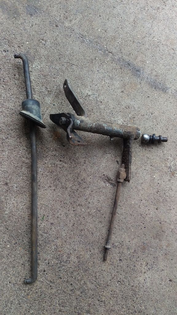 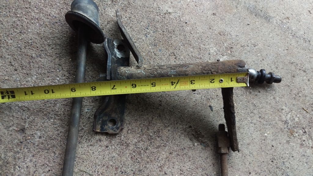 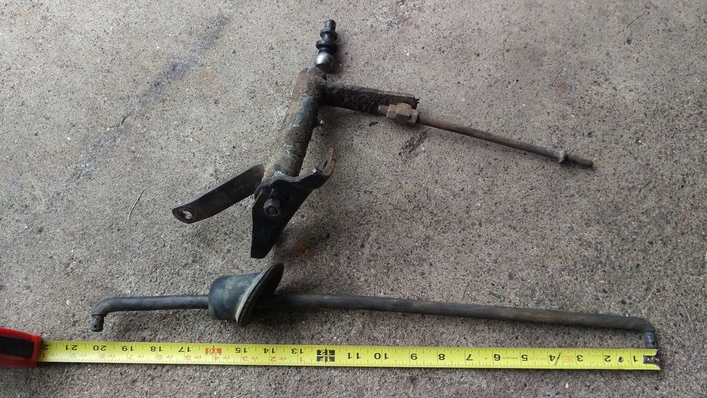 With the ball stud installed in the threaded hole above the oil filter and the bellcrank square to the engine, the frame mount is over an inch out of position. 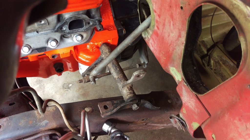 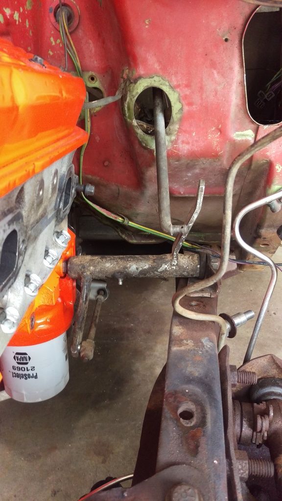 When I install the frame side mount, the bellcrank can't be installed to the ball stud on the engine as it binds up against the shaft of the ball stud due to the diagonal misalignment. The bellcrank seems to be too long for the application. Also note that the ballstud seems a bit long for the application. It came installed on the bellhousing from the NP440 (1984 C10). 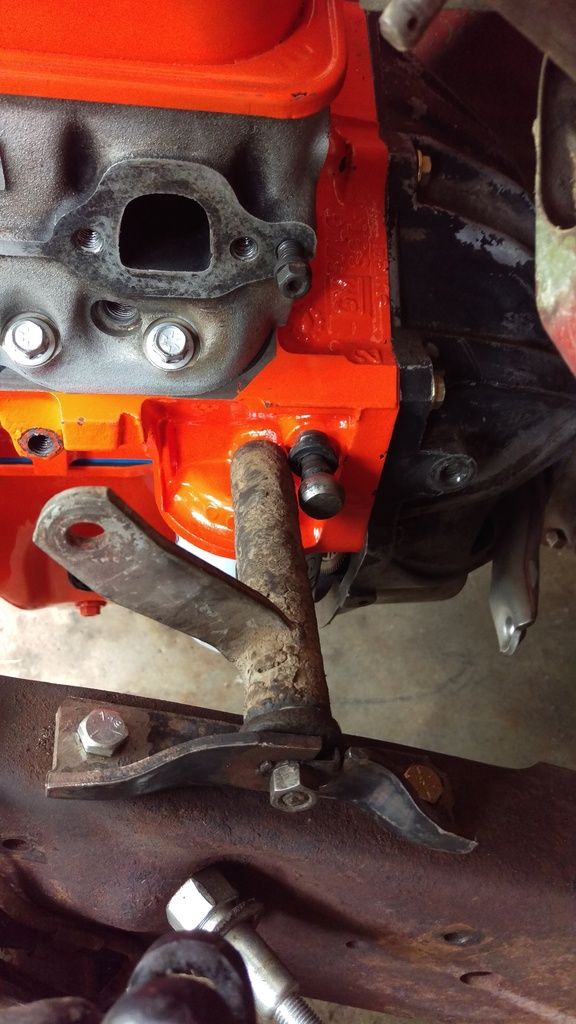 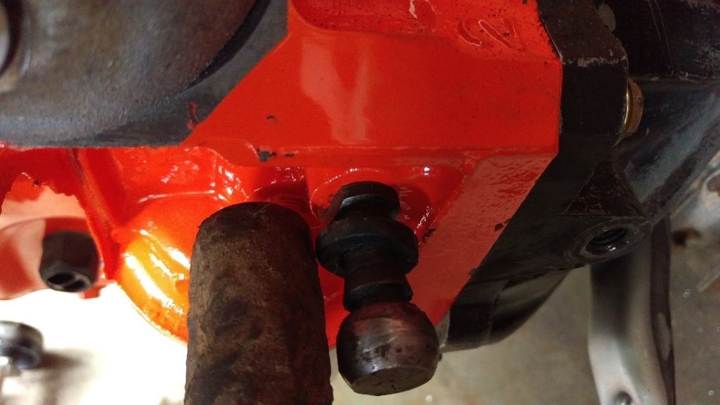 Here is a shot of what I was referring to about the lower push rod and clutch fork. I don't know what is going to keep it from bouncing out, even with a spring load. Maybe I should drill out the dimple and let the rod pass through allowing the to rest on the shoulder? 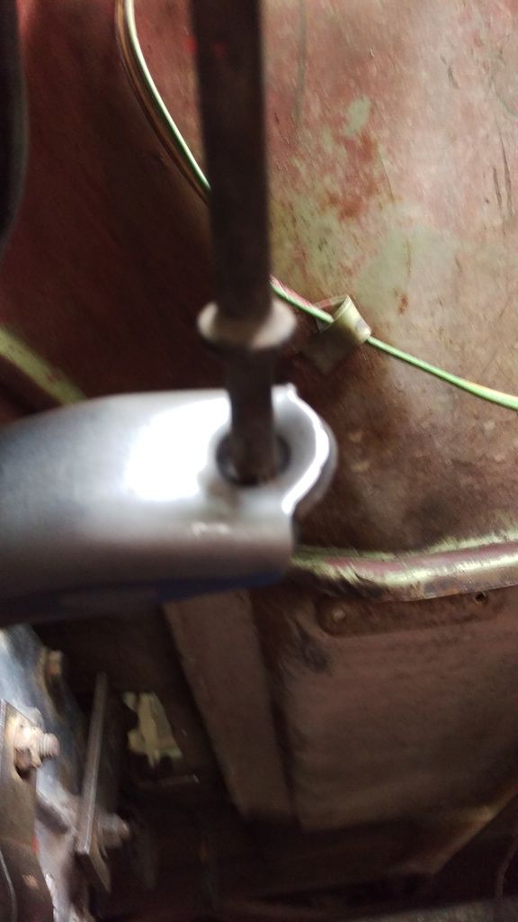 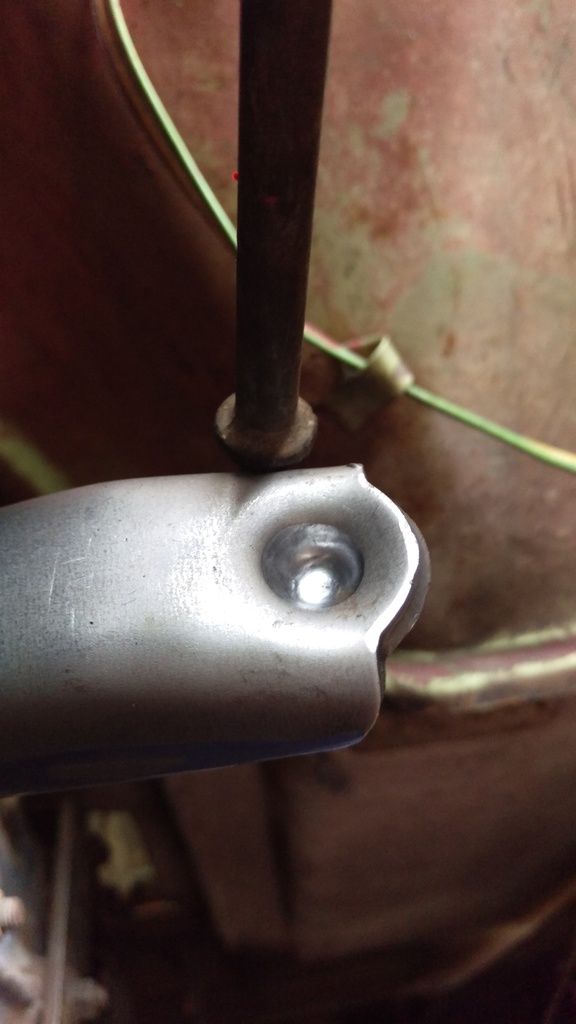 Lastly, the upper push rod has next to no bent to it thus there it can't reach far enough outboard to attach to the belcrank. Other than these issues, it is going pretty well! 
|
|
|
|

|
|
|
#6 |
|
Registered User
Join Date: Aug 2012
Location: St. Croix River Valley, WI
Posts: 795
|
Re: Clutch linkage picture request
Trailcarnage- The "ball stud" in your photos should not go into the engine block by itself like that. It should be mounted to a bracket (basically a flat chunk of steel) that bridges and mounts to the hole you have it in, and the one FORWARD of that hole. I don't think you will use the hole in the bell housing at all.
Hope this helps.
__________________
Meet "Old Roy": http://67-72chevytrucks.com/vboard/s...d.php?t=707801 |
|
|

|
|
|
#7 |
|
Moderator
 Join Date: Jun 2017
Location: Cherryville, NC
Posts: 2,154
|
Re: Clutch linkage picture request
The pics show me you have the chassis mounted bracket backwards...the L slot faces backwards, you currently have it facing forward...
The clutch release rod is retained by the return spring keeping tension on the clutch release fork... Keep on truckin...    
|
|
|

|
|
|
#8 |
|
Moderator
 Join Date: Jun 2017
Location: Cherryville, NC
Posts: 2,154
|
Re: Clutch linkage picture request
Check out the first two pics I posted for chassis bracket orientation...
|
|
|

|
|
|
#9 |
|
Moderator
 Join Date: Jun 2017
Location: Cherryville, NC
Posts: 2,154
|
Re: Clutch linkage picture request
Just noticed in your pics of the bell housing and clutch release fork...that system uses a hydraulic master and slave cylinder system...usually in 85 - 87 trucks...the bell housing has two threaded holes in the side near where the bell bolts to the engine. see LMC truck link ...http://www.lmctruck.com/icatalog/cc/full.aspx?Page=153
If you want to use the manual setup, you will need a V8 bell crank...the one you have appears to be an L6... Notice the difference in the arm shapes and positions in my first two pics...pic 1 is L6...pic 2 is V8 |
|
|

|
|
|
#10 |
|
Registered User
Join Date: Oct 2016
Location: Ontonagon, MI
Posts: 56
|
Re: Clutch linkage picture request
|
|
|

|
|
|
#11 |
|
Moderator
 Join Date: Jun 2017
Location: Cherryville, NC
Posts: 2,154
|
Re: Clutch linkage picture request
Finally...it is really difficult to drill out those release forks as they are hardened during manufacture...
|
|
|

|
|
|
#12 |
|
Moderator
 Join Date: Jun 2017
Location: Cherryville, NC
Posts: 2,154
|
Re: Clutch linkage picture request
The 6 cylinder bell cranks are longer in the tube length than the V8's...
that's the majority of the issue.... if you get the right crank, your bracket can then be turned right way round... Still not sure what to suggest about rod going thru the release fork... I would remove the trans and fork and try drilling it with lots of cutting fluid in a drill press...   
|
|
|

|
|
|
#13 | |
|
Registered User
Join Date: Oct 2016
Location: Ontonagon, MI
Posts: 56
|
Re: Clutch linkage picture request
Quote:
|
|
|
|

|
|
|
#14 | |
|
Registered User
Join Date: Oct 2016
Location: Ontonagon, MI
Posts: 56
|
Re: Clutch linkage picture request
Quote:
|
|
|
|

|
|
|
#15 |
|
Moderator
 Join Date: Jun 2017
Location: Cherryville, NC
Posts: 2,154
|
Re: Clutch linkage picture request
As these trucks have a multitude of engine locations available, it may be better if you place the chassis bracket on the chassis, attach the cross link to the clutch pedal down rod, then move the bracket along the chassis until the lever is approx 90 degrees. Then make a steel bracket to hold the pivot ball.
One of your pics shows the down rod way out of alignment with the cross shaft, I suspect that down rod may be upside down... I suspect the pivot ball and cross shaft is the easier of the fixes...not sure how you are going to drill that clutch fork...   
|
|
|

|
|
|
#16 |
|
Moderator
 Join Date: Jun 2017
Location: Cherryville, NC
Posts: 2,154
|
Re: Clutch linkage picture request
I just went out and took this pic of the layout on my 67 original 327, 3 on tree.
There is a metal bracket mounted on the engine that moves the pivot ball forward about an inch, which looks like it is what your system needs... Maybe put a wanted to buy post out of the forum,,,get the engine bracket, mounting bolts and cross shaft... Only thing I cant see is if your LT-1 has the forward mounting hole in the block... If you cant find anyone willing to see you one, I do intend to go auto with this truck, so I wont need any of the clutch setup...but it would be next weekend before I could get time to pull the parts... Maybe best to check your block for that additional hole, forward of where the cross tube is positioned in one of your pics...maybe another inch or so...   
|
|
|

|
|
|
#17 |
|
Registered User
Join Date: Oct 2016
Location: Ontonagon, MI
Posts: 56
|
Re: Clutch linkage picture request
Aussie,
I cleaned up my components and reinstalled them tonight. With a little cut-n-weld I am sure that I can make then work. With the frame mount installed as you mentioned, the upper push rod lines right up and is near perpendicular to the upper z-arm leaving the lower z-arm parallel to the face of the clutch fork. This looks like pretty clean geometry to me. I figure that I just need to make a ball stud mount for the engine and take s slice out of the middle of the bellcrank. Any chance that I can get a length on the bellcrank tube and hole spacing for the ball stud mount? 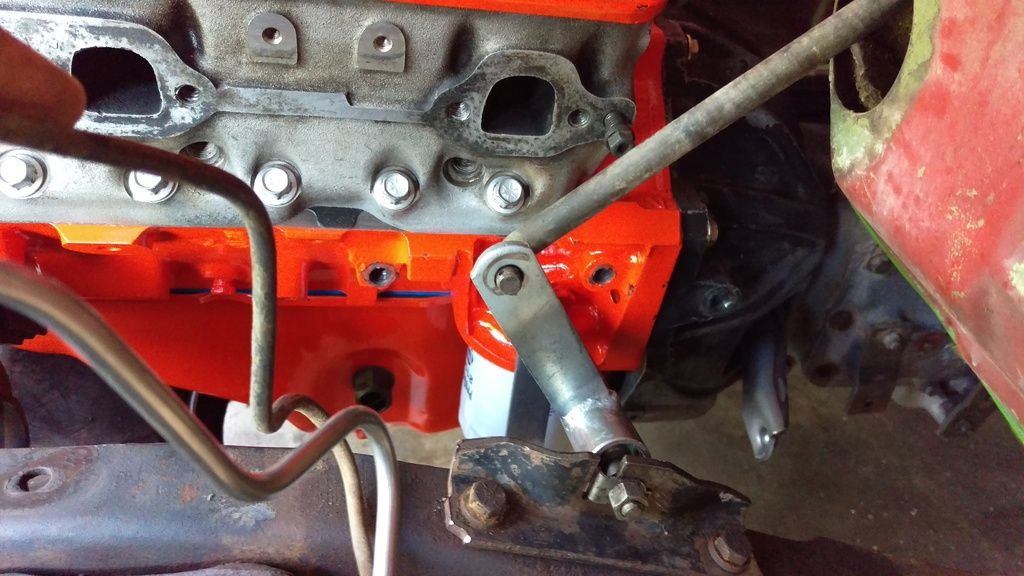 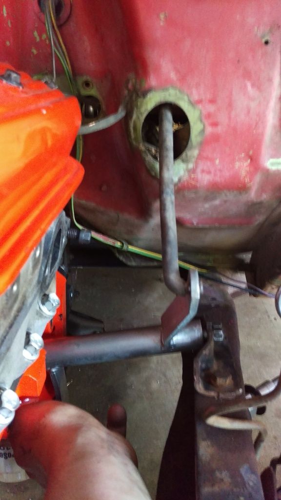 Here's project for reference... 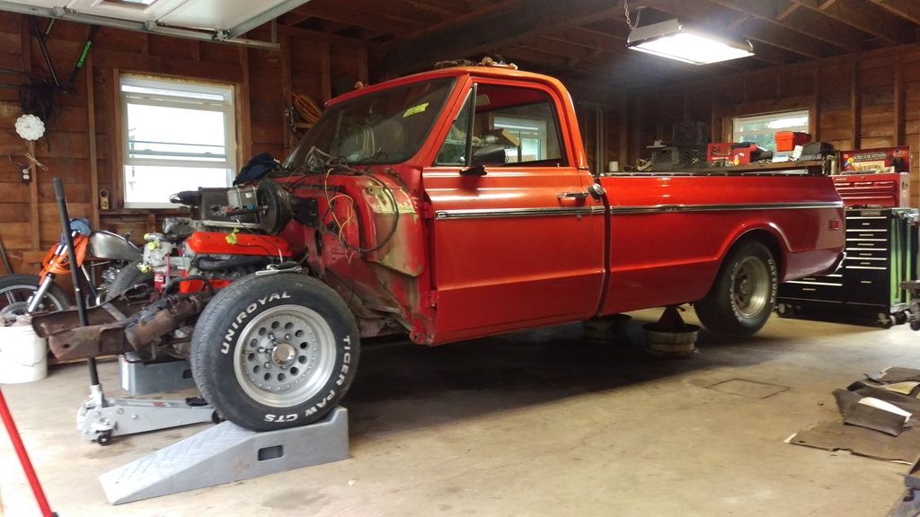 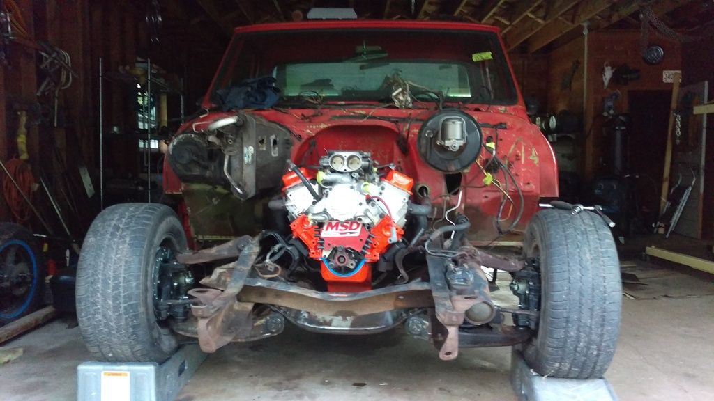
|
|
|

|
|
|
#18 |
|
Moderator
 Join Date: Jun 2017
Location: Cherryville, NC
Posts: 2,154
|
Re: Clutch linkage picture request
You are doing great !
One of your pics shows the front hole in the block to mount the front of the bracket that supports the pivot ball. 3907257 is the GM part number...go look at http://www.4speedconversions.com/68_truck_linkage.html scroll down about half way... You could make one ...you are now on the way young man...   
|
|
|

|
|
|
#19 |
|
Registered User
Join Date: Jul 2016
Location: Olathe, KS
Posts: 267
|
Re: Clutch linkage picture request
I believe the 2WD ball mount on the block is the ball with the plate offset. I used one like that on my 69 custom K10 I built with a 1960 frame.
My son's 70 GMC K20 has the single screw-in ball mounted directly to the block like the OP has shown. I agree that the Z-Bar the OP has appears to be from a 6 cyl based on the Z-arm locations and orientation. It DOES look like an easy fix to get the offset ball with plate from a 69-72 2WD V8 and everything should line up. Don't forget to drill a hole in the clutch fork end so your retaining spring has a place to hook. Normally there is a Vee-shaped anvil that mounts on the end of the clutch rod, but your clutch fork does not work for that. Good Luck!
__________________
1970 GMC K2500 Dis-use is harder on a car than mis-use. |
|
|

|
|
|
#20 |
|
Registered User
Join Date: Apr 2010
Location: So Cal
Posts: 1,412
|
Re: Clutch linkage picture request
AussieinNC, in your first picture with the six, you have the ball bracket bolted to the engine, upside down. That's why the Z-bar is at such a cockamamie angle. If it doesn't break the Z-bar welds, it will surely accelerate wear of the linkage points.
__________________
'67 GMC 2500, 292, 4spd, AC |
|
|

|
|
|
#21 |
|
Moderator
 Join Date: Jun 2017
Location: Cherryville, NC
Posts: 2,154
|
Re: Clutch linkage picture request
The pics I posted were all sourced from this board...I store them to aid some of the folk on here.
They are not pics of any of my current builds or projects... I looked again at that six cyl pic...the bracket is actually bent causing the misalignment...I have a couple of these brackets and they are all setup the same, not offset etc... Stay safe my friend...   
|
|
|

|
|
|
#22 |
|
Account Suspended
 Join Date: Jul 2016
Location: Tacoma, WA
Posts: 6,873
|
Re: Clutch linkage picture request
V8 clutch linkage pics here
http://67-72chevytrucks.com/vboard/s...d.php?t=200386 Note frame bracket is flat on upright part and note orientation, L slot is to rear, V8 is approx symmetrically opposite of 6cyl and flat Note stamped and curved rod to pedal, z bars are similar but 6cyl think is narrower tube. Note proper V8 engine bracket someone described earlier. |
|
|

|
|
|
#23 |
|
Registered User
Join Date: Dec 2013
Location: washington north carolina
Posts: 123
|
Re: Clutch linkage picture request
Great information here.
Looks like I'm going to have to move my bracket mounted to the chassis back and mount a ball in the hole in the block as shown above. I sure hate to move that bracket on my newly painted chassis. Does anyone have the part number of the ball that bolts into the block? |
|
|

|
|
|
#24 |
|
Registered User
Join Date: Dec 2013
Location: washington north carolina
Posts: 123
|
Re: Clutch linkage picture request
Sorry pic is sideways.
|
|
|

|
|
|
#25 |
|
Moderator
 Join Date: Jun 2017
Location: Cherryville, NC
Posts: 2,154
|
Re: Clutch linkage picture request
I would suggest that you dont move the bracket and dont use that threaded hole in the block...
There is a bracket that bolts to the block using that hole and the forward hole, about 4 inches forward on the block. The bracket is available aftermarket...and someone on here may have one to sell. If you can wait a few weeks, I will have one for you, as I am going auto with my build, the truck is currently V8 3 on tree, so it has the cross link and all brackets... Let me know via PM if you want the original one...Thanks   
|
|
|

|
 |
| Bookmarks |
|
|