Distributor curves ahead
Yes there will be math, but trust me its not difficult (smile)
There are many different distributors that you can find on your engine. All the distributors have a mechanical advance, what I would call fly weights controlled by springs. Not all distributors have a vacuum canister, controlling timing advance based on engine vacuum. For street performance you need a distributor with both the mechanical & vacuum canister advance. If you donít have a vacuum advance canister on your distributor, you need to replace the distributor with one that has one.
We are going to be checking and setting the distributor advance curve. Keep in mind that all the distributors work the same concerning how the timing advance is accomplished, but the mechanical advance might not be as easily accessible on all the different distributors. For example some of the L6 engine point distributors have the mechanical advance hidden under the pointís plate, a little bit harder to get to but it can be done. Iím going to be using pictures based on a SB Chevy engine point & HEI distributors but the information applies to all mechanical/vacuum controlled distributors.
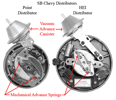
Every distributor that Iíve seen for the street has the mechanical advance springs and a vacuum advance canister, the mechanical advance might not be as easily seen as in the pictures but itís in there, you just have to look for it. The springs and the canister are the two primary items that where going to be looking at and possibly making adjustments to in order to bring the distributor curve to match your engine for street performance.
The largest problems I see is the lack of information by some distributor manufactures either stock or custom relating to timing curves. Or the different numbers used by some to accomplish the same curve but makes understanding and changes questionable and confusing. So the next paragraph of information is very important to understand before you start making adjustments.
As youíre looking at the specification sheet for a distributor or parts like springs or canisters, the first question I ask is the information in distributor degrees/RPM or in engine crankshaft degrees/RPM. The two different kind of numbers can not be used together to figure out your timing curve, you need to convert the distributor degrees/RPM to engine crankshaft degrees/RPM for the tuning described below. To convert distributor degrees/RPM to engine crankshaft degrees/RPM multiply the distributor degrees/RPM times 2, this will convert it to engine crankshaft degrees/RPM. The distributor rotates at half the speed and degrees and the measurements/specifications are often listed as what you would find when using a distributor machine. We need them in a measurement that we can use and verify. If the measurements that your looking at donít include what they are, your going to need to figure it out, using the wrong numbers will not add up to a good outcome (smile).
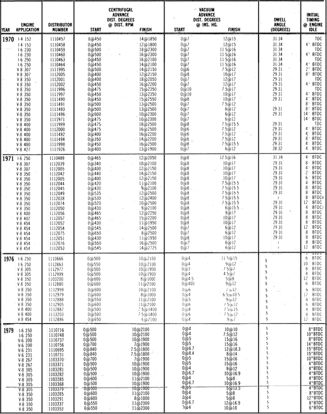
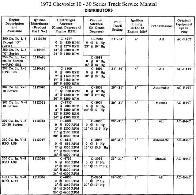
Hear are a few examples of timing curves that you might see from factory settings. There are pages upon pages of different distributor curves you might find categorized by years. The first picture is a few different Chevy years that I put together obtained from (Petersenís all-new 1982 edition, Big Book Of Auto Repair). The 1970 year was the last year before emission changes to timing curves, 1971 was the first year emission changes was introduced, 1976 was one year after the HEI ignition was introduced, and 1979 was the last year that a true mechanical/vacuum advance was used by the factory, in 1980 and on you could find computer controlled distributors (this picture is a list of car distributors only but the truck distributors would be similar). The second picture is out of (1972 Chevrolet 10 Ė 30 Series, Truck Service Manual). You can see how degrees/RPMís are listed differently, the first one by distributor degrees/RPM and the second one by crankshaft degrees/RPM (note all ignition timing/initial timing columns on both charts are in crankshaft degrees).
Time and time again I see people set the initial timing with no consideration or expecting that all distributors are the same regarding advance curves and whatís going on inside the distributor, and then wonder why there engine is not performing as expected. We need to look at all the individual components and how they add up together to create your timing advance. There are only a few degrees/RPMís that we need to look at/measure in order to see the total picture. The first part of the puzzle that where going to be looking at is how many mechanical degrees your distributor has.
With the vacuum canister capped off so that itís not functioning and the idle set at or below 800 RPM, set your initial timing to what ever number of degrees that you feel works the best for you. I find 5 or 10 degrees works for me, this degree is just for taking measurements, not your final setting and this setting needs to be written down. This degree setting number will need to be subtracted from your next reading in order to determine your mechanical advance degrees. Shutoff the engine and remove the springs from the mechanical advance weights, with the springs removed the weights will move out to full advance with the engine at idle. Start the engine and read the timing advance, ether off the timing tape or with an adjustable timing light. You donít need to raise the RPM higher with the springs off. Subtract the initial timing that you set at the beginning from your reading and this is the amount of mechanical advance that you have for your distributor.
You donít have to remove the springs to figure out the number of mechanical degrees that your distributor has, if you have lighter springs than stock spring on your distributor. But you will have to run the engine at a higher RPM to see the advance on the timing mark. I personally donít like to take an engine above 4000 RPM in a no load, sitting in the driveway condition. You can see in the upcoming graph that most of the stock distributors with stock spring would need to be taken to a higher RPM to see the mechanical degrees that a distributor has. If you put lighter springs on your distributor before measuring the mechanical degrees, I would recommend increasing the RPM in 500 RPM steps taking the degree reading at each step along the way and writing them down so you can plot them on the upcoming blank graph. With the springs removed itís a good time to check the fly weights pivot hole and post for wear. A little bit of wear is normal but if it becomes to much the distributor needs to be rebuilt or replaced. How much wear is to much its hard to say in an exact statement, suffice to say if it looks bad to you or something just doesnít look right rebuild or replace it (smile).
The term Total Timing of a distributor is the degree number that Iím most interested in, and this is the degrees that Iím going to be setting my distributor to. Total timing is the distributor mechanical crankshaft degrees + initial timing degrees added together. The number Iím shooting for is total timing of 32 Ė 36 degrees. My distributor has 19 distributor mechanical crankshaft degrees and I picked the total timing of 33, to find out what my initial timing will be I subtract the 19 from the 33 and that equals 14 degrees that Iím setting my initial timing to. Now if I make adjustments to my initial timing, I know how itís going to effect my total timing, to stay within my range of 32 Ė 36 degrees my initial timing would be between 13 Ė 17 degrees. Note some times you might find some talking about a total timing up in the 50s, this is adding on the vacuum advance to the total timing that I describing above (I will be talking about the vacuum advance in the next post).
What is your distributorís number of mechanical advance degrees? With out it you canít set your initial timing correctly. With all the different mechanical advance degrees that can be found on different distributors (stock or custom) you just canít assume that there all a set number or the same. Some distributors have means to adjust the number of degrees with bushings, changing weights or center cams, normally I find no need to play around with this possible adjustment, you can if you like but check/measure it after you make any adjustments.
Now where going to look at when the total advance is applied to the distributor this is based on RPM. This is controlled by the springs that you chouse to install, lighter springs equals advance at a lower RPM and heaver springs equals advance at a higher RPM.
Finding the right springs for your distributor can be a problem. I find that for the stock stile distributors the Crane Cams (PN 99601-1 Crane Vacuum Advance Kit for Delco Points or PN 99600-1 Crane Vacuum Advance Kit for GM HEI) work good to meet my requirements, they can be found at Summit Racing or JEGís. The vacuum canister that comes in the two kits is not my favorite to use but the springs work for me (I will talk about picking a vacuum canister in the next post), sometimes you have to buy a kit with items your not going to use to get the ones you need (smile). If you have a distributor other than a stock stile distributor you will need to contact that distributor manufacturer and see if they have springs for there distributor that will allow you to adjust it to meet the RPM requirements. When all else fails to find the right springs, you will need to start measuring the springs that are in your distributor, first at what RPM do you have total advance in, next do you need to go up or down (heaver or lighter) springs, then measure the spring dimensions (out side spring diameter, spring length, spring wire size), then you will need to find some springs one wire size up or down or more depending on how much RPM you need to change. You might find that you will need to use two springs of different wire size to hit the RPM range, this is OK to do. Where this last approach can fall into the category of trial and error with plenty of checks to see if youíve achieved the right RPM, it can be done. One place that you might find some springs for this approach is at McMaster-CARR in there Ultra-Precision Extension Spring section.
The target RPM that I want total timing in at is 2500 Ė 3500 RPM this is considered to be the range that normally would be found to be cruise RPM at 60 -70 MPH in third or forth the gear with normal gear ratio rear ends and tire size (not in overdrive). My truck driving down the road at 65 MPH in third gear (not in overdrive) is 2900 RPM, I picked the springs that would have total timing in at 2800 RPM. The distributor that I have came with spring in it that had total timing in at 2000 RPM. Sometimes having the total timing coming in at a lower RPM can cause problems in the off idle up to about 3000 RPM range.
The final check is to make sure that all my settings are what I want them to be by running the engine up to 2800 RPM and checking that the total timing is 33 degrees on the timing tape or with a adjustable timing light.
Now with the vacuum canister still capped off, take the truck out for a wide open throttle (WOT) run and check for knocking/pinging. If you run into a pinging problems start backing off the initial timing mark one or two degrees until no pinging occurs. If your total timing is at 30 Ė 31 degrees or below and you still have pinging the problem is not in the timing of having too much timing. Start looking at the gas octane level and the compress ratio or possibly air fuel ratio at WOT. Normally you are not going to be running into a pinging problem with your total timing with in the target area that you can see in the graph. Total timing that an engine can use is directly related to cylinder head combustion chamber shape/configuration and all the Chevy engines of this time 1965 Ė 1979 have similar combustion chambers.
Some history and a visual aid. With all the numbers being thrown around concerning distributor curves I like to plot them on a graph to keep everything straight and see what changes that Iím making, I like to see the difference to a standard. The one standard that I use is what did the factory do. If you look at the below graph all the red dots to the right of the graph are the average crankshaft total timing/RPM by years for the small block Chevy (note if big block or L6 engines where averaged in there, there would be very little difference). The black line is the crankshaft average total timing/RPM for the years before emission changes and the blue line is the average crankshaft total timing/RPM for the years after emission changes. You can see the differences just by year as well as pre-emissions and post-emissions and the general differences that you can run into regarding mechanical crankshaft degrees/RPM. The orange line is the timing curve that I set my distributor to in crankshaft degrees/RPM. The Target Area is what I was shooting for (described above). You can see that the crankshaft total timing degrees in the Target Area and the factory crankshaft total timing (pre-emissions) are a similar range, the primary thing thatís changes is at what RPM the timing is completely in. The yellow line is the average vacuum advance degrees added to the average total timing (pre-emissions) and the green line is the vacuum degrees that I used with my distributor setup (I will be taking about setting up the vacuum canister in the next post).
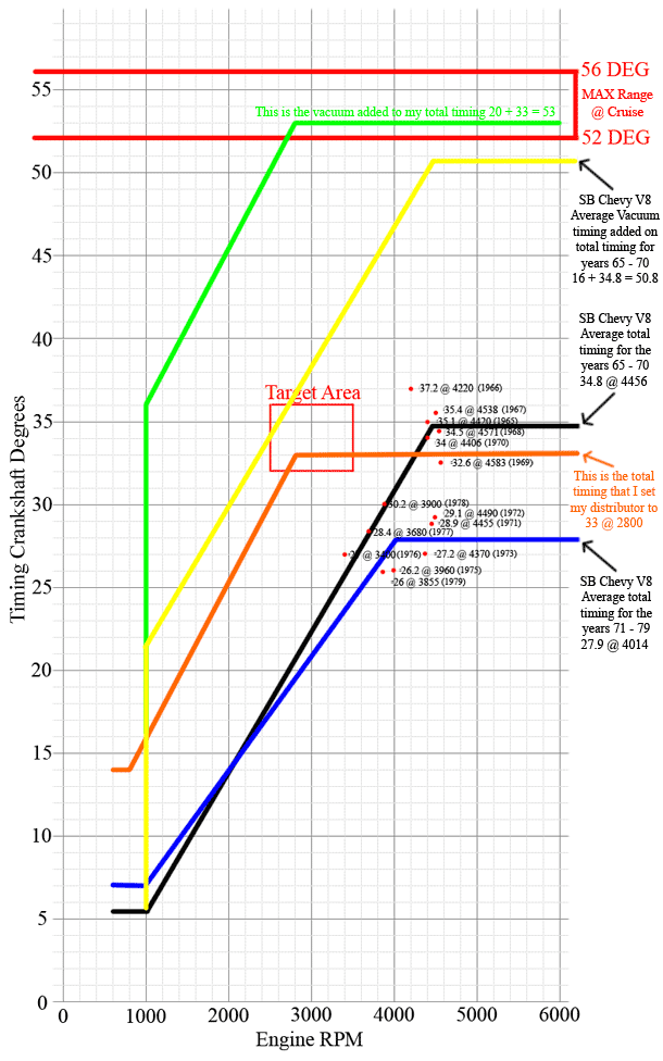
Hear is a blank graph with the Target Area marked on it so that you can plot your distributor curve, possibly a help to you in keeping track of all the different numbers that you run into. You might be asking where this Target Area came from? Over the years hot roders and performance enthusiasts have been looking at improving the performance of the Chevy engines and this Target Area has found its way to being a good compromise for street performance and a benefit to increased performance over stock settings. The Target Area is averaging out (on the conservative side) of a number of different experts concerning street performance curves, some of them are Lars Grimsrud and John Hinckley and you can find some of their article concerning distributor curves by searching the web. They are definitely worth finding and reading concerning distributor curves and performance.
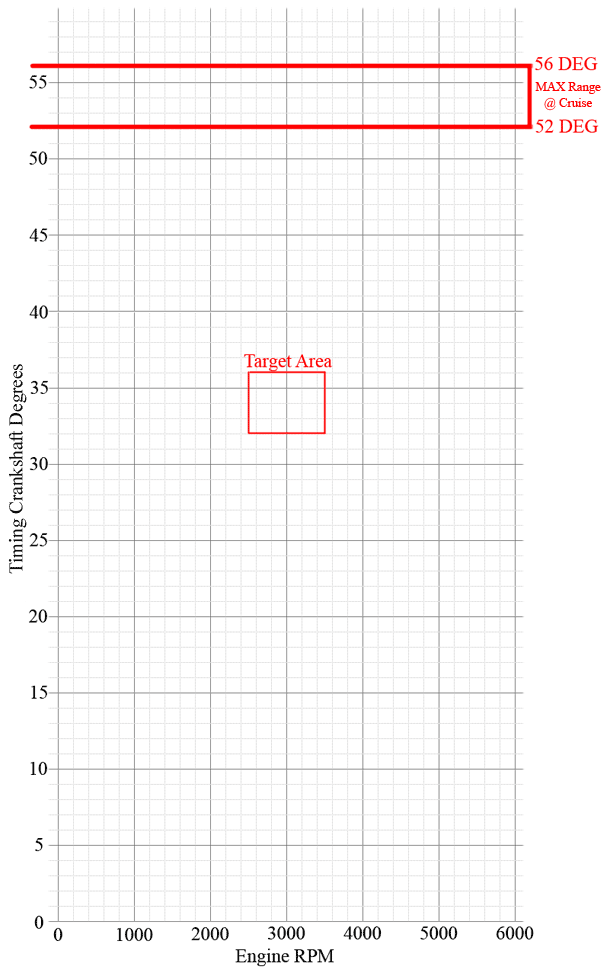
Regardless on what you set your distributor curve to a more conservative or aggressive curve to the one shown above I believe this would be a good starting point for the GM engines and a way that you can figure out what you have and any modifications that you do to your distributor. Knowing what going on inside your distributor can pay big benefits in performance and a good running engine.
In the next post Iím going to be continuing on with the distributor curves but focusing on choosing a vacuum advance canister to work with your engine.
Enjoy your build