Quote:
Originally Posted by rfmaster

Mike
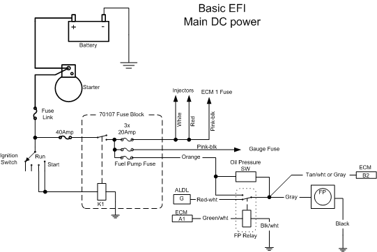
1) Fuel Pump relay wiring
Fuel pump relay socket on a 91 B- Body should have the following wires:
1) black-white (16AWG) | coil ground
2) dark green-white (16AWG) | coil hot - pulled by ECM to +12 V to activate FP relay.
3) Orange (10AWG) (NO - 87)| Battery hot (there should be 20 Amp inline fuse)
4) Red (16AWG) (NC - 87a)| Fuel pump test (4" pig tail with a blade connector)
5) Gray (10AWG) (COM - 30)| Switched Fuel Pump line - this should be connected to FP + terminal.
2) Ignition On Power
I end up wiring a simple relay circuit (see Painless Wiring switched fuse box #70107 for electrically challenged) that gets energized when ignition is on or in start position. For this you'll have to probe your fuse box and find a spare tap port (there should be several ) that remain hot when ignition key is in run and start. This is very important to make sure that this port STAYS hot during cranking!!! Otherwise your ECM will never get a chance to fire injectors during cranking.
3) AC control circuit
Will have to dig into it since B-Body ECM compensates idle RPM when AC is commended to ON. It makes for better idling setup.
//RF |
RF,
I'm a little confused about the pink/black wire in your diagram? Where does it go? I have it tied into the power on during start and run from the fuse box terminal. You show it going to gauge/fuse? I feel like I don't have power hooked up on the ecm somewhere. I can hear the fuel pump relay kick on and pressure up the fuel system. But it won't squirt gas at the injectors.
I think we need to see that we are getting power to them first and then go from there.
Mike