The Engine
Im not making any new friends over at the HAMB with this decision (and maybe some on this board too) but I really like the LS Chevy motors with fuel injection. Ive done a couple of other projects where I used LS engines and was comfortable with making the fuel injection work.
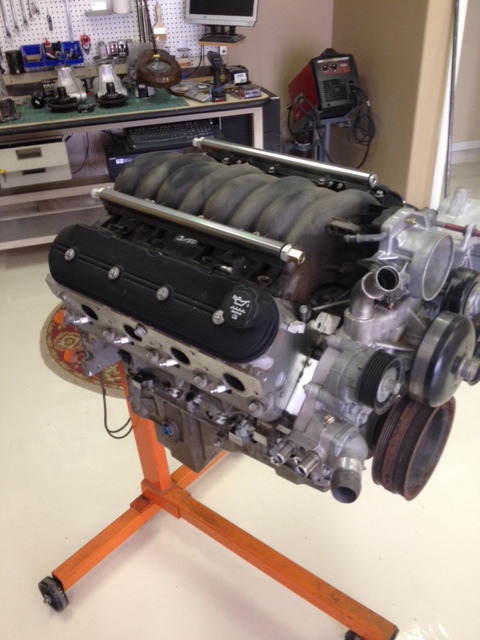
I shopped Craigslist and the local junkyards for a 5.3 truck motor, and finally found an aluminum 5.3 with 95K miles out of a Trailblazer for $650 at a local junkyard. The truck accessories and a wiring harness and ECU from a drive by cable throttle from a Suburban set me back another $100.
I cleaned it up and installed a Corvette intake and shaved the valve covers of the coil mount bosses I plan to remote mount the coil packs to clean up the engine bay still havent figured out exactly how Im going to do this.
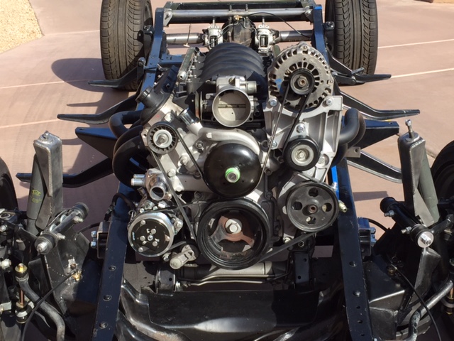
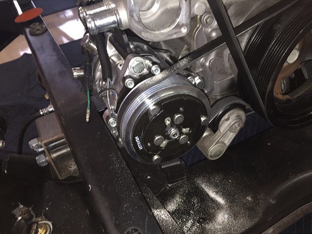
Without buying an expensive aftermarket accessory drive, I didnt see how anything but the truck accessory layout would work in the 49. All the truck accessories cleared in the mockup stage, but since the truck pulley and accessories protrude more than the f-body or Corvette, I moved the engine further back into the firewall to give more room up from for the accessories and cooling fans. This also gave me a little more room for headers and a low mount ac compressor by taking advantage of the taper in the frame rails. This is the near-final accessory drive Im using-
The Corvette intake positions the throttle body such that he throttle lever hits the water neck of the truck pump. I tried heating the trucks stainless water neck to see if I could move it in the housing, but gave up when it looked like all I was going to do was crush it. A water pump from a 2009 Trailblazer solved the problem with a different location of the discharge tube.
After I put on the Corvette intake with the Suburban throttle body, the belt routing for the accessory drive hit the throttle body. A cheap idler relocation bracket from ebay fixed that problem. (If youre really paying attention, you might notice the belt routing is incorrect in this photo)
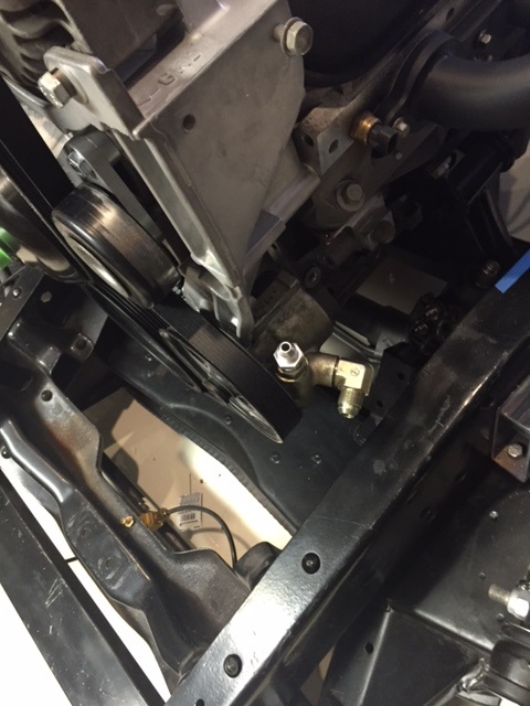
I know this sounds ridiculous, but the plastic power steering reservoir mounted on the pump looks entirely too modern for the engine bay. I took it off and put on a AN-8 fitting on the suction side of the power steering pump so I could fit a remote reservoir. For other projects, Ive made reservoirs out of two round halves of aluminum AC driers welded together, so thats what Ill do for this truck too.
I was too cheap to spring for the $175 air conditioner bracket that Alan Grove sells so I fabricated my own. I had to shave two of the ears off the Sanborn compressor to get it to clear the frame rails, but it does clear.
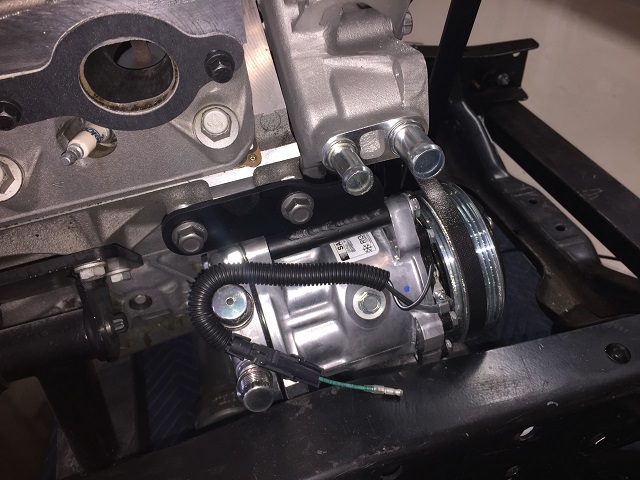
I used the truck belt tensioner on my bracket.
Headers were my biggest challenge. Id used Corvette sheet-metal headers on my LS Jag conversion but I couldnt make them clear both the motor mount and the steering rack on the driver side on the truck. I didnt want cast manifolds either. Pacesetter is here in Phoenix and makes long tube headers and shortys for the LS motors and I went there and bought a pair of shorty Camaro headers. They fit, but the collector interfered with the stock pedal arm (wanted the original pedal setup for the nostalgic look) so I took them back.
The Pacesetter sales manager offered to let me try a pair of Camaro long tubes they fit too but the collector on the drivers side hit the brake booster bracket on the chassis. Back again, and he gave me some GTO headers to try, but the collector was wrong and wouldnt fit. With any of these solutions, Id need to snake the steering shaft around with a lot of u-joints too. Too many compromises.
Id built headers before for turbo systems, aircraft and sand rails, but nothing with as many constraints as the LS motor in an old GMC truck with narrow frame rails, an archaic pedal setup and a Jaguar rack and pinion, but decided to give it a shot.
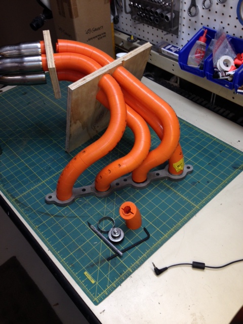
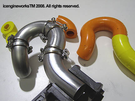
I started with some stainless flanges, cheap ebay merge collectors and a header lego kit from ICEngineworks in Texas. With the engine and the front suspension in the truck for mock-up I tried numerous configurations to get the primary lengths to be all around 28 or so inches and have a single steering shaft to the rack from the column with just two u joints. Heres one of my first attempts with a design that would have gone through the inner fender well-
And another configuration in legos on the bench-
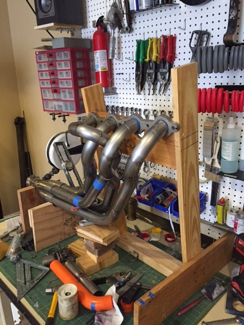
I got tired of getting up and down from the floor to trial fit header tubes in the truck, so when I got a configuration that was close, I built a wooden fixture on my workbench to do the final fit from the comfort of a chair. Once I got the legos to all fit, I transferred the dimensions onto 304 stainless mandrel bends, cut them on my Portaband mounted in my Swag base and then sanded them on a belt sander to get a perfect fit for welding with the TIG.
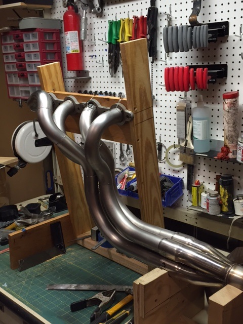
I had a hell of a time getting the tubes to fit together for tacking. Mandrel tube isnt perfectly round, and when you mate a straight section to a cut through a curved section, the fit-up of the tubes is always a best fit compromise. I bit the bullet for these clamps and it helped immensely.
Heres the finished drivers side headers in the chassis tacked but not welded (the small tube in the middle is where the steering shaft goes)
I was going to run bare stainless headers and simply glass bead them and polish them up with a Scotch-brite, but when the final welds were done, there was an aw **** moment when I realized Id somehow picked up a piece of mild steel mandrel and used that for one of the bends. Rather than ordering another mandrel bend, cutting it out and welding in the correct stainless one, I was so darned tired of screwing with headers I had them ceramic coated black. They still look good and will last forever, but that mistake was a rookie move.
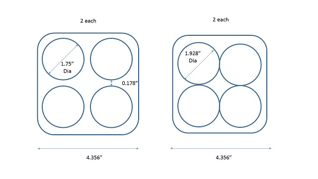
I had planned on using slip on collectors, but was too cheap to spring for $600 for a pair of good ones from Burns Stainless. The Chinese ones from ebay looked ok, but where the primary tubes slide inside them was a sloppy fit to the headers and I didnt see how Id ever get them to seal up, even with a barrel full of red RTV. A local ATV shop has a plasma table and cut these clover-leafs out of 3/16 plate so I could weld the cheap slip-on merge collectors to the header primaries.
Added some O2 sensor bungs and they were done.
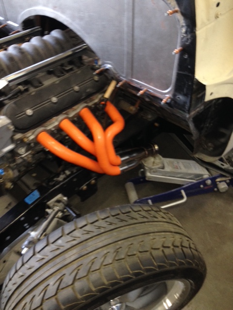
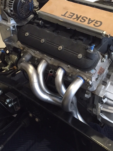
Heres a picture of the final headers in the chassis.
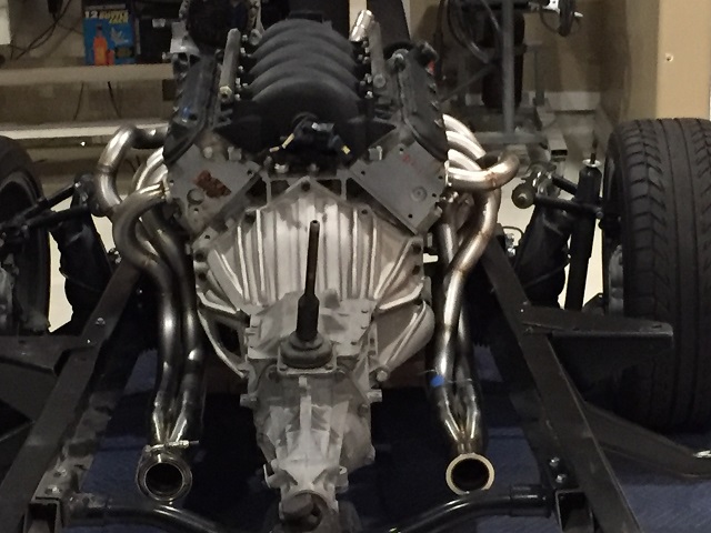
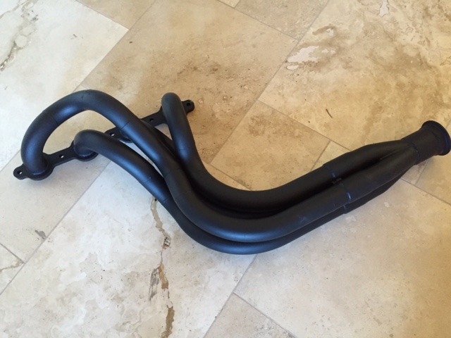
The final coated header- drivers side
The transmission is a T5 from a 1980s V8 Camaro with a S10 tail-shaft support to move the shifter to a more forward location for a truck. This transmission is rated a 300 ft-lbs and is probably not the optimum choice for the LS motors torque and horsepower. But theres some method in my madness. Im old and just want to put-put around my clutch side-stepping stoplight launches are far behind me. The clutch, hydraulic TO and bell housing will work with a T56 or a TKO transmission too, so when Im ready to change it I wont have to buy those too. If I dont trash the T5, I can sell it to someone that wants if for their six cylinder truck - it has much better ratios than the S10 T5s.
The bell housing is a reproduction GM 621 that I got from Kiesler, a Sachs 1050 flywheel for an LS truck and a big block Chevy clutch. The big block clutch on the LS flywheel is a bit of a compromise because the big blocks clutch disk overlaps the LS flywheel area only about 80%. With the torque the 5.3L motor puts out vs the big block, I dont think it will be a problem.
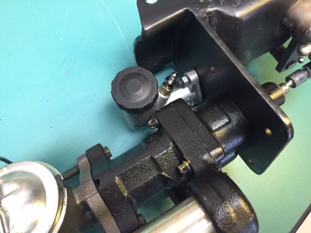
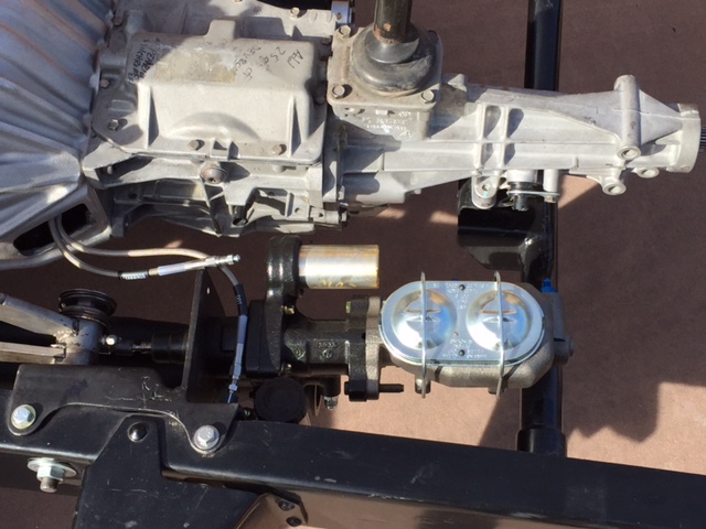
The truck came with a small diameter under cab brake booster, but I had some misgivings on how that was going to work with four wheel disc brakes. I harvested a Hydroboost from an Astrovan at a local junkyard and fabd the linkage to use with the trucks pedal setup. For the master, I used a 1.125 diameter Corvette from about 1980.
Heres a pic of the Hydroboost and master cylinder installed in the chassis- you might notice the Hydroboost is installed upside down, but thats so the accumulator can clear the clutch master cylinder. The guys on Pirate 4x4 say it doesnt make any difference and works equally well either way
Next up - the suspension