Quote:
Originally Posted by PurdueSD

First off, thank you both very much! Im still really confused however. @dmjlambert. The plug that you are saying is the incorrect one, came from my donor vehicle, the same donor vehicle as the alternator. The original Engine harness that i cut the plug from was unaltered. The S and P terminals in the plug dont have a wire in them at all...
|
If you look at the first sentence of Of what I posted you will see that there were two types of plugs PLIS and SFLP. You have a SFLP plug that was the donor plug in the harness that you cut which was unmolested.
You also stated that the P and the S slots in the plug were uninhabited. If you read the quoted again you will see that the F slots were not used in some vehicles and the P slot was used for accessories like a tach so it is entirely possible that the vehicle did not have those features
The purpose of the S terminal is for voltage sensing on the vehicle circuits which tell the alternator's internal regulator what the circuit voltag is and to increase or decrease it accordingly. Some vehicles read that data off the vehicle main junction via the ECM so the S terminal was not used. Some of the later year CS alternators had features that red the circuit voltage off the large output wire on the alternator. Your alternator might be one of those or it might not.
In any case, look at the terminals inside the alternator where the plug goes and see if you have the four terminals and if so you only need the L and the S terminals and in fact you may only need the L terminal if the alternator is post 1994. It would not hurt to run a sensing wire to the S terminal anyway. It would be constant hot from some hot source preferably the main junction of the battery and alternator.
You will definitely need to connect an ignition on source with a resistor inline to the L terminal to be the alternator exciter circuit.
I don't see any way that connecting it like that will hurt the alternator or the harness.
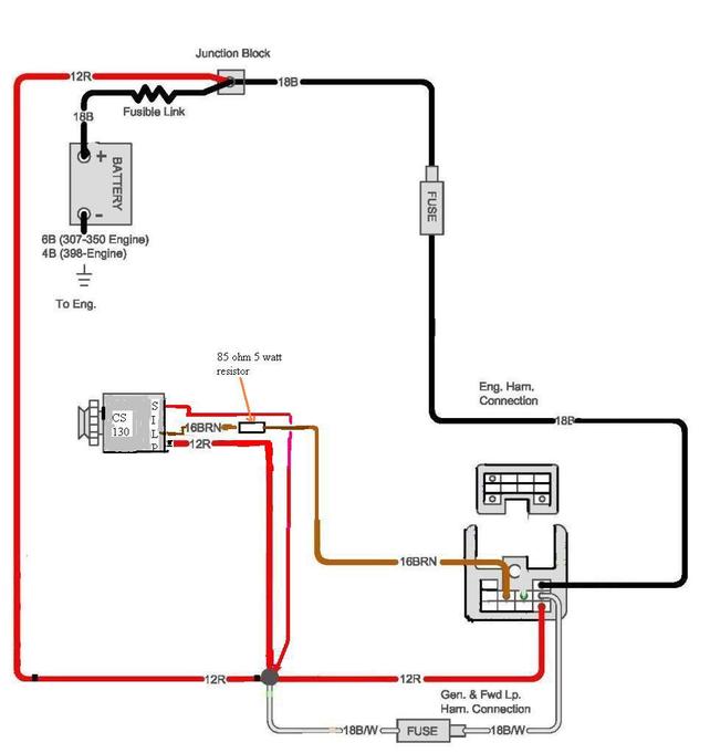
If it were me I would locate an alternator plug from a vehicle that matches the alternator and splice in these two wires to the alternator. The S and L wires. Here is the diagram I use to describe the conversion. It has been used by countless people and it works.
The brown wire from the firewall is the exciter wire from the ignition switch, and it shows the resistor wired inline to the L terminal and the other S wire comes from the main junction.