
|
|
|
 11-30-2012, 09:28 PM
|
#1 |
|
Registered User
Join Date: Oct 2003
Location: OC CA
Posts: 1,374
|
Re: Tbi swap build thread
You will need the DRAC to convert AC 4000 ppm signal coming from VSS. The DRAC will provide correct 2000 ppm square wave signal to the 7747 ECM. You do not need 90+TPI ECM. DRAC will also provide 4000 ppm square wave signal to the electronic instrument cluster from 90 burban. Alternative to DRAC is a dakota digital SGI-5 can do the same without DIY alteration of the DRAC to account for tire size, rear end gear ratio and VSS reluctor gear.
Problems Crane cam 100052 has duration @0.050 216/216 with LSA of 110. This is a good carburetor camshaft, but it will make MAP sensor very unhappy! I am going to guess your idle vacuum is only 12 to 13 in-Hg at 700 RPM with plenty lopping. Even modified 7747 will have problems at idle. The kicker is 216 duration and tight 110 LSA. If budget permits go for a cam with duration around 210/210 and LSA more than 112 deg. You'll loose a little bit of top end power, but your idle will smooth out. Close alternatives are Comp Cam 12-365-4 Lift I/E .499/.493 Duration @0.050 216/220 LSA 113 deg If you heads can not take this much lift Speed Pro CS1013R can be a good candidate Range 2000-4500 RPM Duration @.050 214 intake/224 exhaust, Lift I/E 0.443 /0.465 LSA 112 Disabling EGR is straightforward in EPROM. To get the full power of this engine expect to DIY tune. Please be aware that Vortecs do not require too much timing ~ 32 deg maximum at 3000 RPM vs 36+ for conventional heads. Thirdgen.org has extensive articles that covers this in fine detail. //RF
__________________
"The Beast" 1975 Chevrolet C20 longbed 350/700R4! with 3inch body lift Dual Flowmasters Super 40's! TBI retrofit completed (2007-07-29)  New 383CID (+030) 08-304-8 9.5:1CR x36,005 (2012-12-17) |

|

|
|
12-12-2012, 03:41 PM
|
#2 |
|
Registered User
 Join Date: Jun 2007
Location: lemoore ca
Posts: 126
|
Re: Tbi swap build thread
Has anybody used the 88-95 headers with this swap? Just wondering because I would rather use headers with the o2 bung already installed vs retrofitting one on the pipe after the collector.
|
|
|
|
|
01-13-2013, 07:01 PM
|
#3 |
|
not enough hours in the day
Join Date: Jan 2009
Location: Axtell, NE
Posts: 550
|
Re: Tbi swap build thread
I have a couple questions about my swap. The engine is out of a 88 pickup and going into my 70 Blazer. The air pump was not hooked up and I am going to remove it and use stock 70 manifolds. I tested the EGR valve and it does not operate with vacuum applied. I drove the pickup before pullling the engine and it ran good.
Is the EGR valve necessary, or would I be OK just blocking it off?
__________________
65 K-10 Short Step 68 C-50 70 K-5 85 K-10 & piles of spare parts |
|
|
|
|
01-13-2013, 07:06 PM
|
#4 |
|
not enough hours in the day
Join Date: Jan 2009
Location: Axtell, NE
Posts: 550
|
Re: Tbi swap build thread
My 88 engine has two temperature senders. This one in the intake
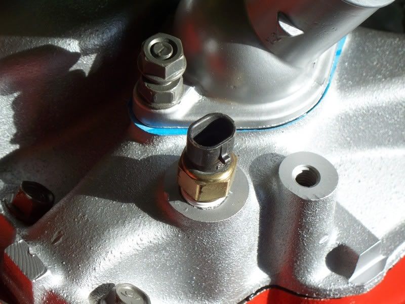 and this one in the head 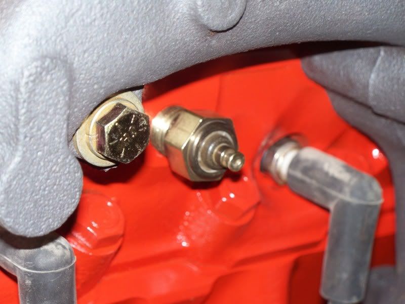 Is the one in the intake for the computer and the one in the head for the guage? It also has this oil sening unit by the oil filter 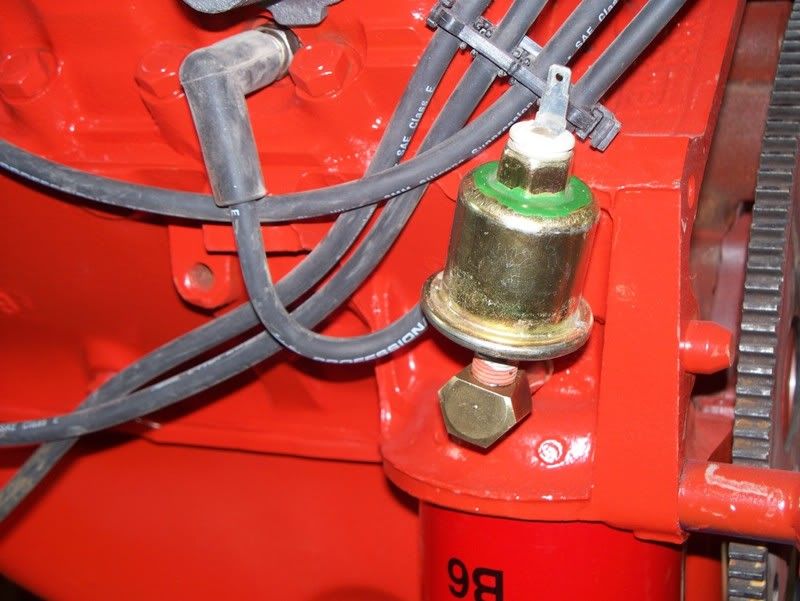 Is this for the guage and can I eleminate it for the mechanical guage?
__________________
65 K-10 Short Step 68 C-50 70 K-5 85 K-10 & piles of spare parts Last edited by jasons; 01-13-2013 at 07:15 PM. |
|
|
|
|
01-13-2013, 07:12 PM
|
#5 |
|
Registered User
Join Date: Mar 2010
Location: molino florida
Posts: 7
|
Re: Tbi swap build thread
No you do not need egr. If you wish to use your stock intake manifold you can get a block off plate for it or get an aftermarket intake that doesn't use egr. I assume you're using th tbi with ecm so you may have to remove egr from the ecm via a flash, or new prom.
Posted via Mobile Device |
|
|
|
|
01-13-2013, 07:42 PM
|
#6 |
|
not enough hours in the day
Join Date: Jan 2009
Location: Axtell, NE
Posts: 550
|
Re: Tbi swap build thread
I belive the prom has been changed, but I know noting about it. If I block off the egr and don't flash the ecm what problems would this cause. I'm thinking a new egr for $50 would probably be easier and no more expensive than sending the prom off somewhere to be flashed. Are there any benifets one way or the other?
__________________
65 K-10 Short Step 68 C-50 70 K-5 85 K-10 & piles of spare parts |
|
|
|
|
03-12-2013, 11:42 AM
|
#7 |
|
Registered User
Join Date: Oct 2003
Location: OC CA
Posts: 1,374
|
Re: Tbi swap build thread
Ok Guys.
This thread has been languishing for a while so I've decided to add a bit of swap related information. It has been mentioned that bolting L31 - vortec heads (casting # 602, 906) nets 40+ HP over stock smogger heads. This swap has been covered extensively by performance magazines and countless gear heads elsewhere. This is a great swap for some one on the tight budget, but it is not without its pitfalls. A stock TBI system uses swirl port heads, but will adapt nicely to Vortec heads. To use L31 heads on Gen 1 block (assuming 350 CID TBI) will require standard head gasket and vortec specific intake manifold and intake gaskets. If the EGR valve is to be retained exhaust gases will have to be plumbed via custom pipe to EGR inlet port on the manifold. If EGR is to be omitted modification to EPROM will be required. All of the above has been covered before. The issue is that our trucks use 1/2 NPT sized temperature sending units that screw into driver side head providing resistance vs. temperature signal to the instrument cluster gauge. Original GM sending unit is no longer available (GM 1513321) and the closest equivalent is AC-Delco G1852. Aftermarket produces similar units such as Wells TU5, SMP TS6 among many others. None of these sending units will screw into Vortec heads which are drilled and tapped for 3/8 NPT sensors. It has been suggested that 1/2 NPT sensor units can be turned down on a lathe. However, not everyone has a access to one. Drilling and tapping Vortec Head for a larger sensor (1/2 NPT) can be problematic - sensor boss area is very small and CI can be unforgiving. This begs a question -are there any 3/8 NPT temperature sending units that will work with square body temperature gauges??? In the past it has been suggested that a Ford F5CF-10884-AA , F5CZ-10884-A, Motorcraft SW5051 can be a possible substitute. Lets take a look if it is even close to what we need. Test setup - side by side TU5 vs Motorcraft SW5051 mounted into the same AL block. 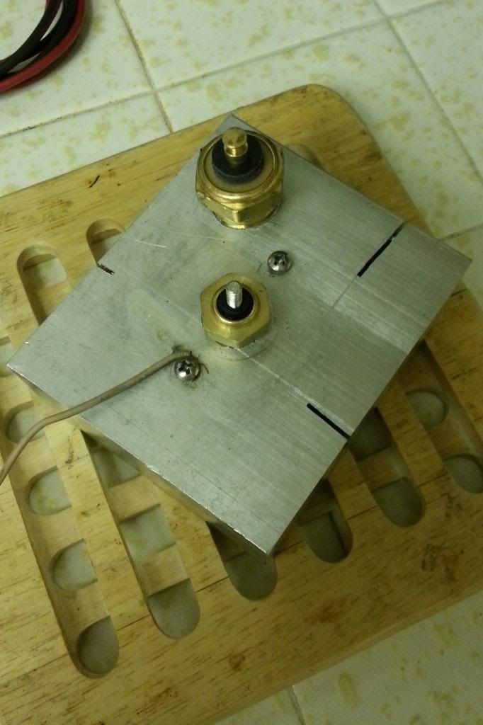 Measurement setup 2x Fluke 70 DVM + Fluke 52 Temp sensor meter (in my kitchen - the old lady gave a permission). Ideally, I would rather do this characterization testing in the environmental chamber which allows for soaking at a specified temperature, but it is not available at this time. 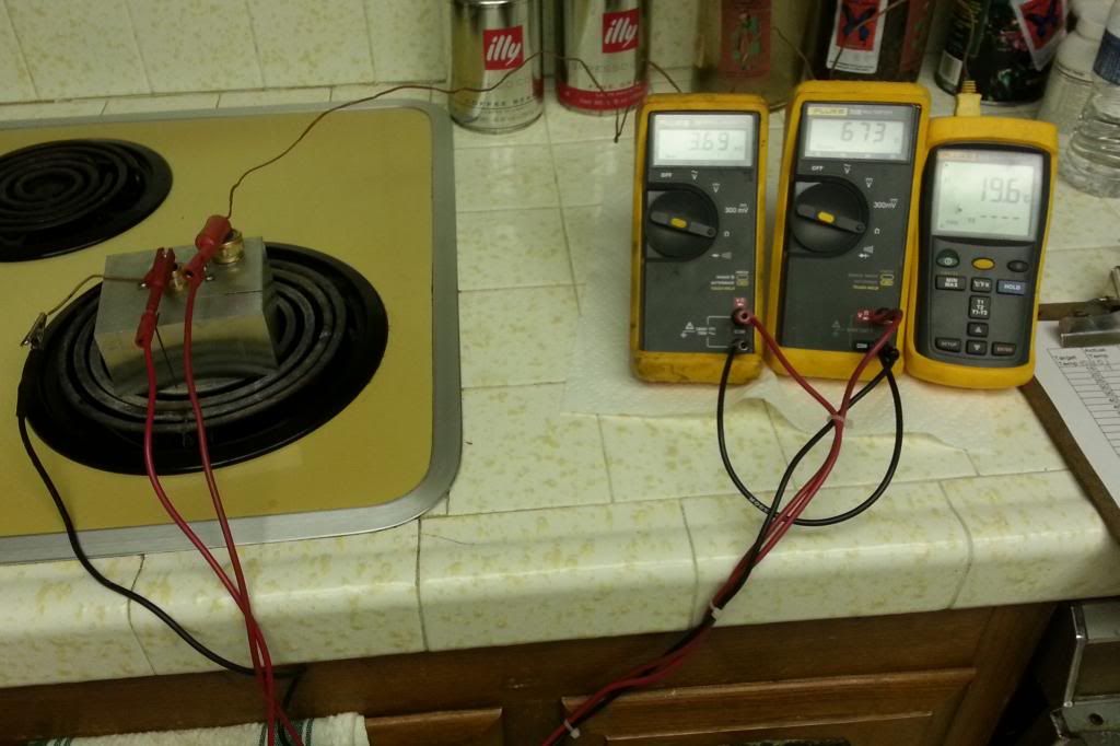 Test result speak for themselves. When engine coolant is below 50C SW5051 has high resistance which result in a lazy gauge (not reading anything), but above 78C the SW5051 has lower resistance and would result in a higher indicated temperature then it really is! 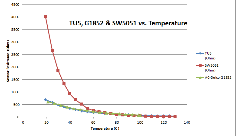 Zooming into high temperature coolant area. 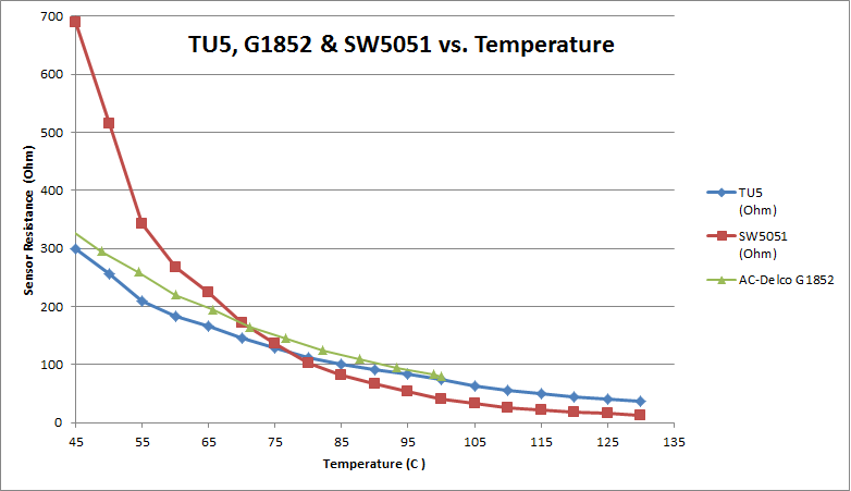 Cross over occurs right around 76 to 80C region. AC Delco G1852 (found on Internet) data stops at 100C (212F) - I do not have this sensor at this time, but would like to re-run it to see how it behaves between 100 and 135C. Next step is to validate SW5051 with the actual gauge. Suggestions???? Questions??? //RF
__________________
"The Beast" 1975 Chevrolet C20 longbed 350/700R4! with 3inch body lift Dual Flowmasters Super 40's! TBI retrofit completed (2007-07-29) New 383CID (+030) 08-304-8 9.5:1CR x36,005 (2012-12-17) |
|
|
|
|
04-10-2013, 05:00 PM
|
#8 | |
|
not enough hours in the day
Join Date: Jan 2009
Location: Axtell, NE
Posts: 550
|
Re: Tbi swap build thread
Quote:
__________________
65 K-10 Short Step 68 C-50 70 K-5 85 K-10 & piles of spare parts |
|
|
|
|
|
04-11-2013, 02:17 AM
|
#9 | |
|
Registered User
Join Date: Oct 2003
Location: OC CA
Posts: 1,374
|
Re: Tbi swap build thread
Quote:
RED line is the temperature curve for SW5051 with a series 22 Ohm resistor added. Below 75C (165F) the temperature gauge will be displaying very low temperatures due to higher resistance offered by SW5051. Above 75C with 22Ohm series resistor SW5051 appear to track TU5 very closely. 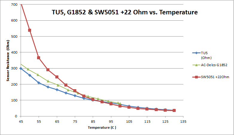 I have not had a chance to verify this, but test data supports this conclusion. //RF
__________________
"The Beast" 1975 Chevrolet C20 longbed 350/700R4! with 3inch body lift Dual Flowmasters Super 40's! TBI retrofit completed (2007-07-29) New 383CID (+030) 08-304-8 9.5:1CR x36,005 (2012-12-17) |
|
|
|
|
|
04-11-2013, 08:27 AM
|
#10 |
|
not enough hours in the day
Join Date: Jan 2009
Location: Axtell, NE
Posts: 550
|
Re: Tbi swap build thread
Thanks RF. I was thinking around 30 Ohm would be needed. I'll get a resistor to add and post the results.
__________________
65 K-10 Short Step 68 C-50 70 K-5 85 K-10 & piles of spare parts |
|
|
|
|
04-11-2013, 01:08 PM
|
#11 | |
|
Registered User
Join Date: Oct 2003
Location: OC CA
Posts: 1,374
|
Re: Tbi swap build thread
Quote:
//RF
__________________
"The Beast" 1975 Chevrolet C20 longbed 350/700R4! with 3inch body lift Dual Flowmasters Super 40's! TBI retrofit completed (2007-07-29) New 383CID (+030) 08-304-8 9.5:1CR x36,005 (2012-12-17) |
|
|
|
|
|
03-18-2013, 12:49 PM
|
#12 |
|
Registered User
Join Date: Feb 2013
Location: Mandan
Posts: 80
|
Re: Tbi swap build thread
when u ran new lines did u run steel or were they rubber. just asking because i did a swap and need to move the tank but they are all steel and was wondering if i cut out and replace with rubber
|
|
|
|
|
03-18-2013, 01:04 PM
|
#13 | |
|
Registered User
Join Date: Oct 2003
Location: OC CA
Posts: 1,374
|
Re: Tbi swap build thread
Quote:
//RF
__________________
"The Beast" 1975 Chevrolet C20 longbed 350/700R4! with 3inch body lift Dual Flowmasters Super 40's! TBI retrofit completed (2007-07-29) New 383CID (+030) 08-304-8 9.5:1CR x36,005 (2012-12-17) |
|
|
|
|
|
03-23-2013, 12:52 PM
|
#14 |
|
not enough hours in the day
Join Date: Jan 2009
Location: Axtell, NE
Posts: 550
|
Re: Tbi swap build thread
I have a plug from my doner 88 pickup harness that I'm not sure what to do with. One wire goes to the computer labled Air Pump and the other is labled EGR Relay. Did this plug into the air pump? I dont have it anymore to check and it wasn't being used on the donor vehicle. Can these two wires be eliminated or do they plug in somewhere I'm missing?
__________________
65 K-10 Short Step 68 C-50 70 K-5 85 K-10 & piles of spare parts |
|
|
|
|
03-23-2013, 05:48 PM
|
#15 | |
|
Registered User
Join Date: Oct 2003
Location: OC CA
Posts: 1,374
|
Re: Tbi swap build thread
Quote:
1) do nothing - just let them flop or tape them to the harness. 2) Remove connector ends and tape-up end of the wires and hide them in the main loom. Simple enough and quick. //RF
__________________
"The Beast" 1975 Chevrolet C20 longbed 350/700R4! with 3inch body lift Dual Flowmasters Super 40's! TBI retrofit completed (2007-07-29) New 383CID (+030) 08-304-8 9.5:1CR x36,005 (2012-12-17) |
|
|
|
|
|
03-23-2013, 08:23 PM
|
#16 | |
|
not enough hours in the day
Join Date: Jan 2009
Location: Axtell, NE
Posts: 550
|
Re: Tbi swap build thread
Quote:
__________________
65 K-10 Short Step 68 C-50 70 K-5 85 K-10 & piles of spare parts |
|
|
|
|
|
03-25-2013, 06:41 AM
|
#17 |
|
Registered User
Join Date: Feb 2013
Location: Mandan
Posts: 80
|
Re: Tbi swap build thread
truck starts and runs great , but when going down the road and wanting to step hard on the gas truck bogs way down , but if u ease in to it easy it runs fine, here is my couple of questions, i used a wiring harness from 90 suburban,put it all on after wards i had to add 12 volts to the injectors, and to the fuel pump relay. and tie my fuel pump wire in to the relay .then it started right up.but i do not thing it is right, at end of harness for tbi goes in to the fuse box and right now that is not attached to nothing, not exactly sure on how to wire up that tbi,also i dont have the trouble shooting plug are the check engine light hooked up . does that go to end of harness some wear,can some one give me some info on hooking up this tbi harness,
|
|
|
|
|
03-25-2013, 11:21 AM
|
#18 | |
|
Registered User
Join Date: Oct 2003
Location: OC CA
Posts: 1,374
|
Re: Tbi swap build thread
Quote:
It is tough to diagnose what you have going - can you upload couple of good quality photographs of what you have setup and connected? The part of any swap is to document and capture what you have done as when something goes bad you'll have a way to troubleshoot. From memory - I have pulled 90, 92 burban engine bay harness before. The plug that bolts into firewall bulk head connector (reference designator C100) under brake booster is used ignition and starter solenoid. Ckt #3 Pink Ignition coil ckt #430 pink-blk fuel injection power ckt #120 tan-white Fuel pump supply ckt #330 orange Battery B+ (always hot) //RF
__________________
"The Beast" 1975 Chevrolet C20 longbed 350/700R4! with 3inch body lift Dual Flowmasters Super 40's! TBI retrofit completed (2007-07-29) New 383CID (+030) 08-304-8 9.5:1CR x36,005 (2012-12-17) |
|
|
|
|
|
03-25-2013, 09:44 PM
|
#19 |
|
Registered User
Join Date: Feb 2013
Location: Mandan
Posts: 80
|
Re: Tbi swap build thread
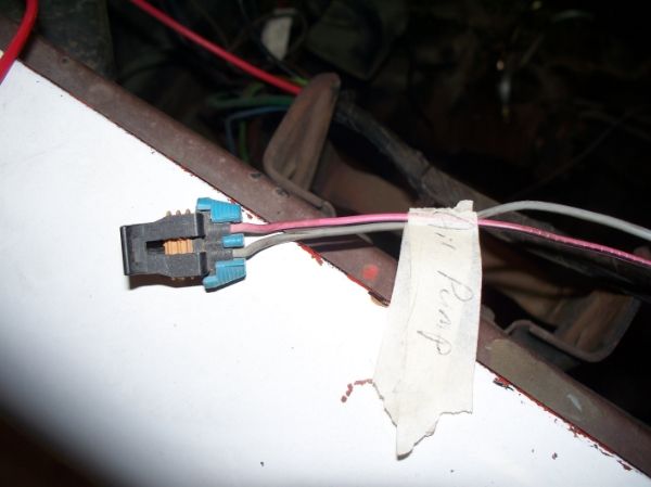
ok this is what iv got going , i have read some what every body is written and iv gotten some info, some other questions are about the alternator 90 suburban has 2 wires that come out the side of alternator have been cut and just laying there, I also have the original harness from the 72 on the truck , thoes wires that go 2 the alternator is a fat red that bolts to back and a plug white and a blue wire that would plug in to the 72 style alternator, what do i do with all these wires, the plug on the alternator that is there now from the suburban i under stan needs a ground and the other goes to a light is that right, and what do i do with the wires to the 72. they look like they go to the stock 72 voltage regulator that is in the pic '' black box''. and do i need to hook up the o2 sensor and the park neutral switch to the computer, was reading , if park neutral is not hooked to computer then the computer doesnt read the vss and then wont adjust for timing .. I sure thank evrey body for there help .
|
|
|
|
|
03-26-2013, 02:30 AM
|
#20 |
|
Registered User
Join Date: Oct 2003
Location: OC CA
Posts: 1,374
|
Re: Tbi swap build thread
@BigrobDog
OK - thanks for posting photographs - these help quiet a bit. In Photo # 1 Your 1990 burban donor came equipped with CS-130 Alternator. This alternator has internal regulator. OE external '72 regulator that you have in Photo #2 will not be used. To adapt CS 130 to the '72 wiring is actually straight forward, but it will require a bit of DIY soldering. Are you up for it???? CS130 alternator is rated for 105AMPS maximum output and will deliver around 30 to 35Amps at idle. Which is plenty. Look at the back of alternator. There, you should see BAT terminal and big fat red wire should be running between alternator BAT terminal and terminal block that is part of EFI harness - mounted on the passenger side firewall. I thinks there is one, but it is taped-up and not clearly visible. That wire should have been a part of '90 burban harness. From the firewall mounted terminal block there also should be a big red wire running to starter main terminal - its also should be a very thick red wire - 8AWG. Please take a close look and capture a photo of it in case if it is not connected. A fuel pump relay should be in close proximity to that firewall mounted terminal block. Back to CS-130 alternator. There is a multi pin plug with several wires protruding from it.. Most often it is just a brown 16 AWG wire tied to 'L' terminal. This is a alternator light bulb wire. You can NOT connect this wire directly to the instrument alternator light. This connection can only be made if there is a series 150 to 300 OHM 1Watt resistor ( between alternator plug and instrument cluster alternator light). This is done by disconnecting external regulator plug from OE external regulator module and connecting brown wire from CS-130 'L' circuit with a series resistor to terminal 4 of the OE regulator plug - also brown wire. At least GM was consistent with their wire color schemes over decades! . Schematic below does not show this resistor, but it must be there.  Sometime, there is a larger gauge red wire tied to S terminal - this is a voltage sense line. This wire should be tied to a BAT terminal block on the firewall. Photo #3 This is a tough one - this portion of the harness was connected to 90 burban main feed through block. The wires protruding maybe useless - anti lock computer, windshield wiper motor, temperature sensor, etc. It is best to remove split loom and peel off electrical tape and determine where these wires went. VSS - this is a long discussion in itself. Do you have 700R4 from donor or you still have THM-350/400??? P/N switch - some DIY is involved but can be easily implemented. Search this thread for schematic. //RF
__________________
"The Beast" 1975 Chevrolet C20 longbed 350/700R4! with 3inch body lift Dual Flowmasters Super 40's! TBI retrofit completed (2007-07-29) New 383CID (+030) 08-304-8 9.5:1CR x36,005 (2012-12-17) |
|
|
|
|
03-26-2013, 06:50 AM
|
#21 |
|
Registered User
Join Date: Feb 2013
Location: Mandan
Posts: 80
|
Re: Tbi swap build thread
no i have the 700r4 . its all suburban put 72 over the top
|
|
|
|
|
03-26-2013, 10:58 AM
|
#22 | |
|
not enough hours in the day
Join Date: Jan 2009
Location: Axtell, NE
Posts: 550
|
Re: Tbi swap build thread
Quote:
__________________
65 K-10 Short Step 68 C-50 70 K-5 85 K-10 & piles of spare parts |
|
|
|
|
|
03-26-2013, 11:17 AM
|
#23 | |
|
Registered User
Join Date: Oct 2003
Location: OC CA
Posts: 1,374
|
Re: Tbi swap build thread
Quote:
http://67-72chevytrucks.com/vboard/s...d.php?t=436742
__________________
"The Beast" 1975 Chevrolet C20 longbed 350/700R4! with 3inch body lift Dual Flowmasters Super 40's! TBI retrofit completed (2007-07-29) New 383CID (+030) 08-304-8 9.5:1CR x36,005 (2012-12-17) |
|
|
|
|
|
03-26-2013, 11:40 AM
|
#24 |
|
not enough hours in the day
Join Date: Jan 2009
Location: Axtell, NE
Posts: 550
|
Re: Tbi swap build thread
Thanks again RF. I hadn't seen that thread. Glad to know this before firing it up and wondering why it didn't charge properly.
__________________
65 K-10 Short Step 68 C-50 70 K-5 85 K-10 & piles of spare parts |
|
|
|
|
03-26-2013, 09:53 PM
|
#25 | |
|
Registered User
Join Date: Feb 2013
Location: Mandan
Posts: 80
|
Re: Tbi swap build thread
Quote:
|
|
|
|
|
 |
| Bookmarks |
|
|


 Hybrid Mode
