
|
Register or Log In To remove these advertisements. |
|
|
|
|||||||
|
|
Thread Tools | Display Modes |
 01-02-2012, 03:08 PM
|
#1 |
|
Registered User
 Join Date: Mar 2005
Location: apple valley, ca
Posts: 2,670
|
My caster mod (with pictures)
On Rob's Make It Handle thread, he mentioned that if he were to ever do a mod to increase caster, he would move the lower arm forward and the upper arm aft. This got my brain spinning, and I decided to do the lower arm mod. Here's what I did:
To start, I disassembled the lower control arms and blasted everything clean. Take a note of the locations of the factory-located spot faces, as they are going to change to a new location on the shaft. 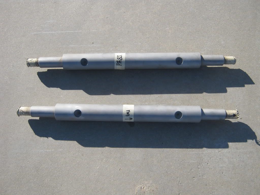 I sent the shafts to a friend who is a machinist. The intent is to move the lower control arm forward .75", so the spot face holes will need to move .75" on the shaft. I discovered that the factory spot faces on my shafts did NOT line up with the locating pins on the crossmember at both the forward and aft locations. Only the front actually used the pin, and the aft point was not a pin at all, just a raised area that acted more like a spacer instead of a locating pin. I wanted positive pin retention, so it was important that both front and aft points pinned into the cross shaft. Here's what you need to do: First, spin the cross shaft 180 degrees opposite of the factory spot faces so you have a nice clear area to work with. Then, make your .75" measurement from the centerline of the aft hole. Remember, you're moving the arm forward, so the new spot face will be closer to the edge of the cross shaft in relation to the original factory spot face. Once you have set this measurement, you must go to the crossmember and measure the center-to-center distance between the front and aft pins. My measurement was 9.0" exactly. So, for the forward spot face hole, I went 9.0" from the centerline of the newly located hole. Here is a side-by side shot of the factory locations versus the new locations. The upper shaft is the factory location, the lower shaft is the new location. 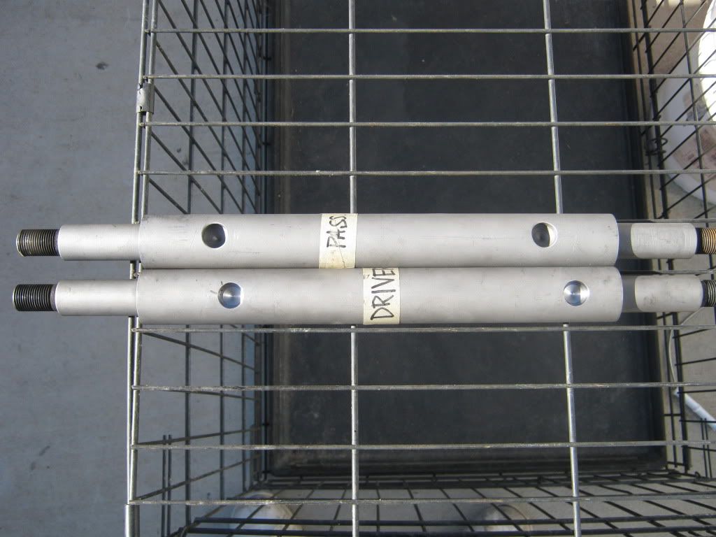 In order to do this mod, you have to remove the saddles that are riveted to the center crossmember. The lower control arm cross shafts are kept from spinning by a stud that locates itself in the spot-faced holes in the lower control arm shaft. Here, you can see a picture of the front crossmember showing the two bolt holes for the u-bolts and the rivet head for the locating stud I mentioned earlier. The stud side is not visible in this picture. 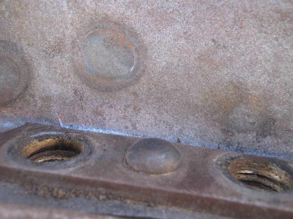 In order to get the saddles removed, you have a few options. You can grind the heads off and drive out the rest of the rivet. Or, you can fire up the torch and melt the rivet heads off, then drive out the rest. I opted for the torch. I learned quickly that even with the head and tail of the rivet melted off, the rivet stems did not come out without a fight. I had to warm up the rivet stem with the torch and shoot them out with an air chisel. The rivets go through 4 layers of steel (doubler plate, saddle, and and 2 layers of the crossmember). Once you get them out, here's what the pieces look like after a few minutes in the blaster: 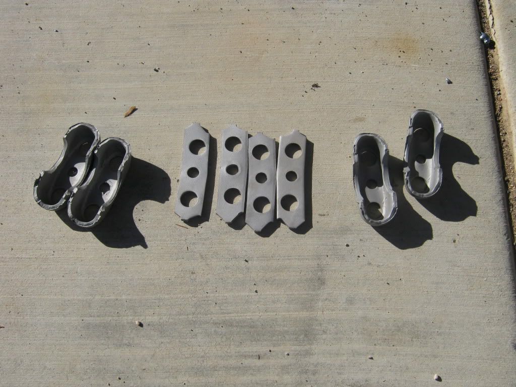 Here's what you'll see when the saddles, doubler, and rivets are removed. I decided that I was going to use a 7/16-20 X 1.50" socket head cap screw as the new locating pin, so the center hole in this picture needed to get opened up to a 7/16 to ensure that bolt would fit nice and tight. The light area in the front is the lip on the crossmember, which will be cut away. Sorry for the dark picture, my lighting was a little goofy. 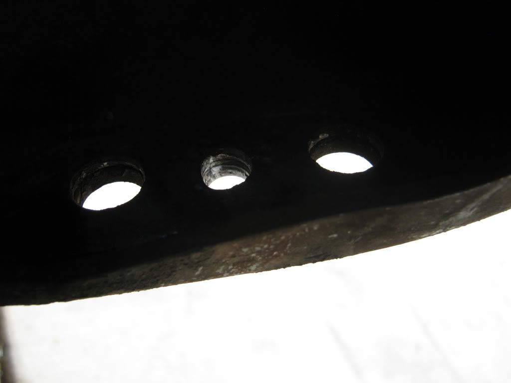 Moving the control arm forward will cause the aft side of the control arm to get really close to the center crossmember, so I removed the lip and blended out the cut to eliminate any sharp edges that could cause a stress riser. You will only need to cut the lip back to where it meets the second metal layer. 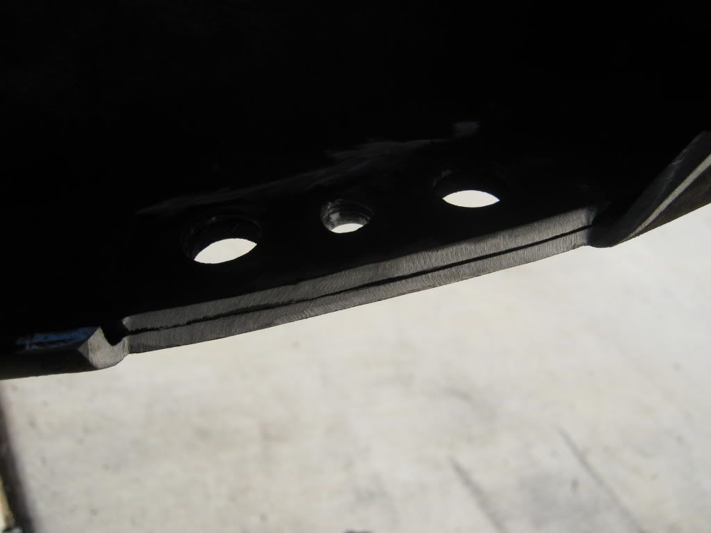 Here's a shot of the saddles back in place on the crossmember. This shows the bolt in place of the old rivet locating pin. For added insurance, I used Loctite and a stover nut. Here's a shot of the finished installation: 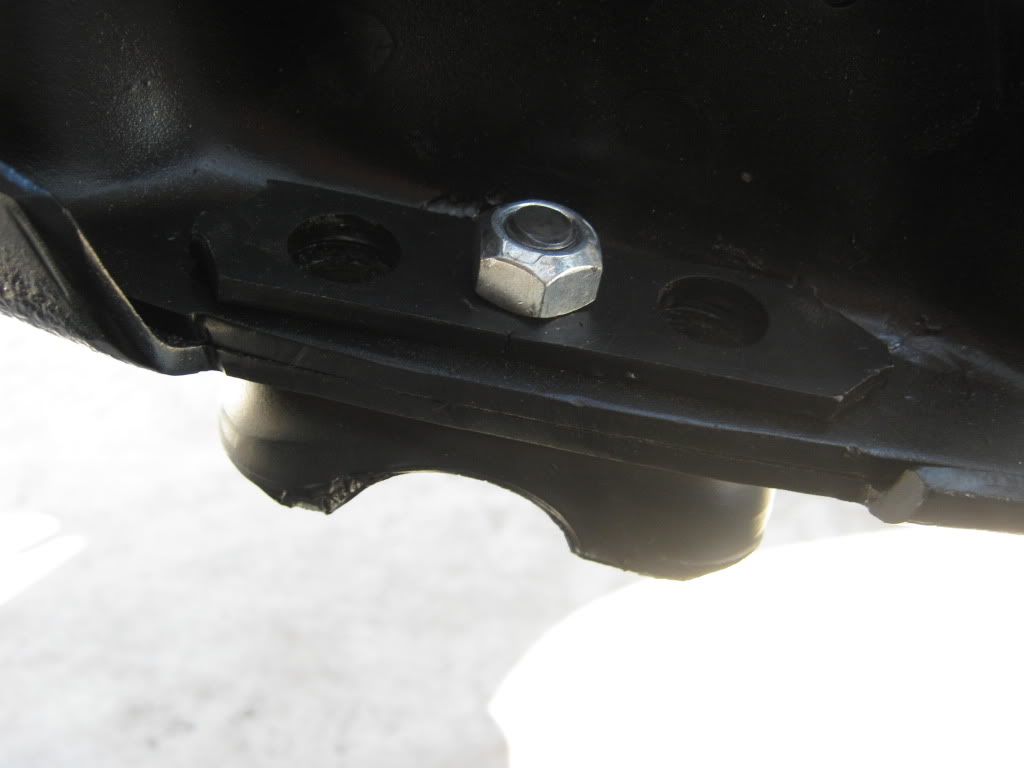 In this shot, you can see the head of the fastener, which will locate perfectly in the new spot face positions in the lower control arm cross bar. 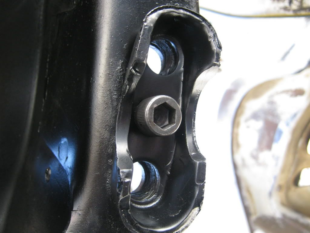 While the control arms were out, they got blasted and painted. New Energy Suspension bushings were installed and all the balljoints were replaced with Moog parts. Then the moment of truth arrived, and it was time to install the control arms and see if the caster mod was a success. Everything fit perfect. The clearances were excellent, and the locating pins lined up exactly as planned. Here is a shot of the driver's side control arm. You can see just how much the control arm moved forward. 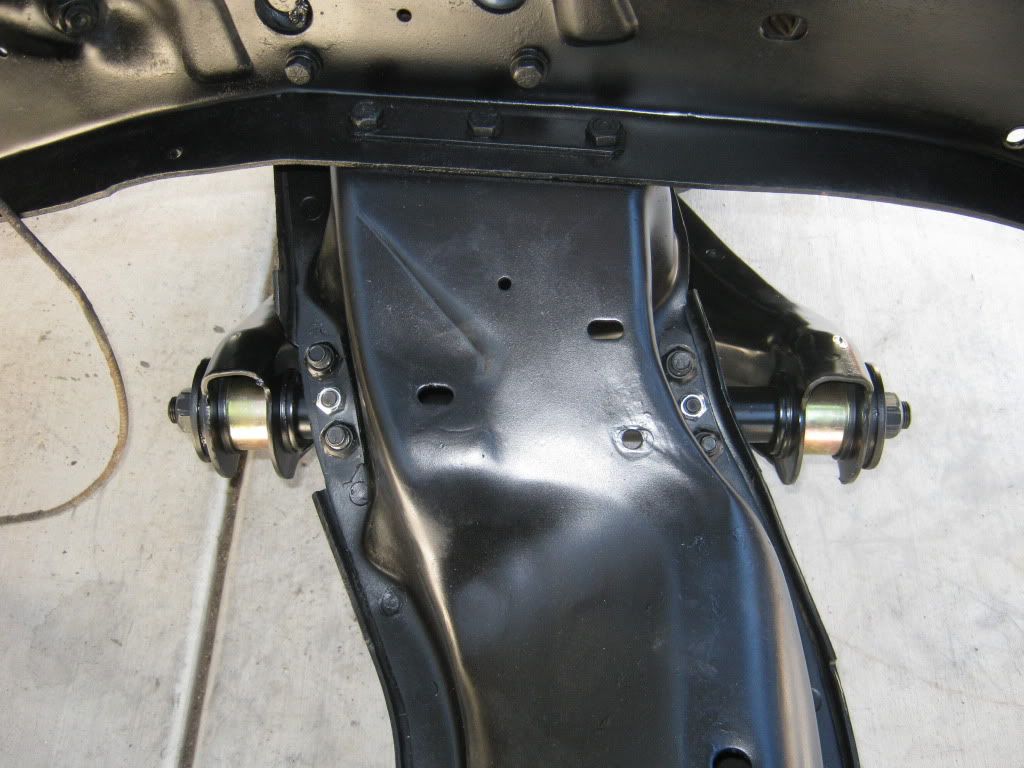 Here's a close-up shot of the back-side. If you recall, I had to clearance the crossmember. I now have plenty of room with the control arm at full up/down. 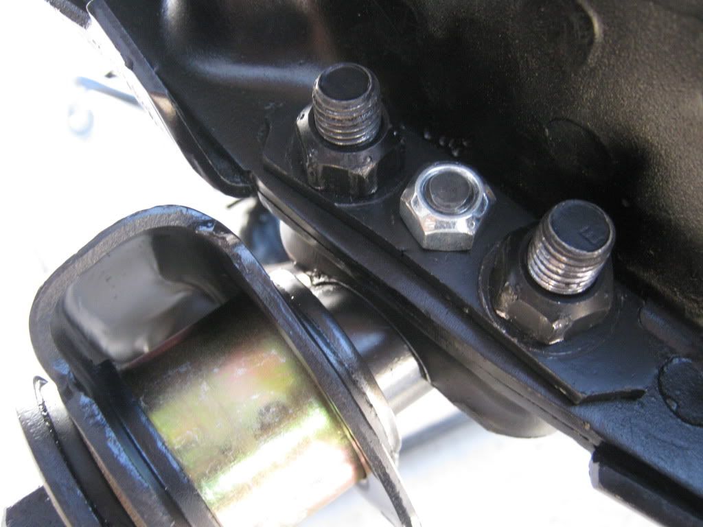 Here's a shot of the front side. You can really the .75" difference in position from stock. 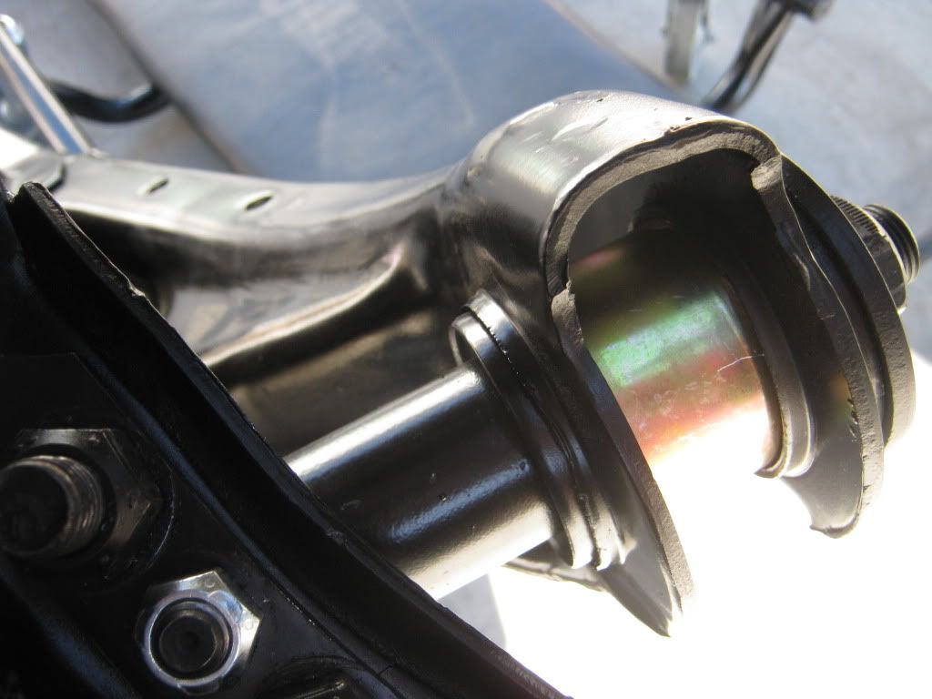 Here's another thing I did to eliminate a huge shim stack in the upper control arm. On the 1973-up half-tons, GM utilized spacers on the control arm bolts, along with the normal shims. Because I cut a coil from the stock spring, I knew that the alignment shop would have to add more shims to get the camber correct. So, I went to the wrecking yard and grabbed some other spacers(the fat ones) and added them to the mix. The original set-up was: 1 skinny spacer on the forward bolt, and one fat spacer on the rear bolt. The new set-up is: 1 fat spacer on the front, and 1 fat and 1 skinny spacer on the rear. Not much of a difference, but I don't like the look of a huge spacer stack on lowered vehicles. It moved the arms out about 1/4" of an inch. 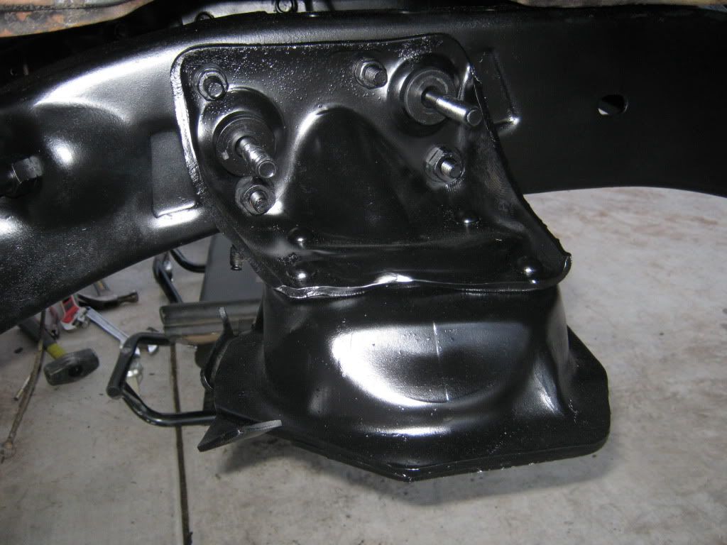 Not a great picture, but you can see the offset between the upper and lower balljoint centerlines. This shows you how much the spindle will tilt aft, thus increasing caster. 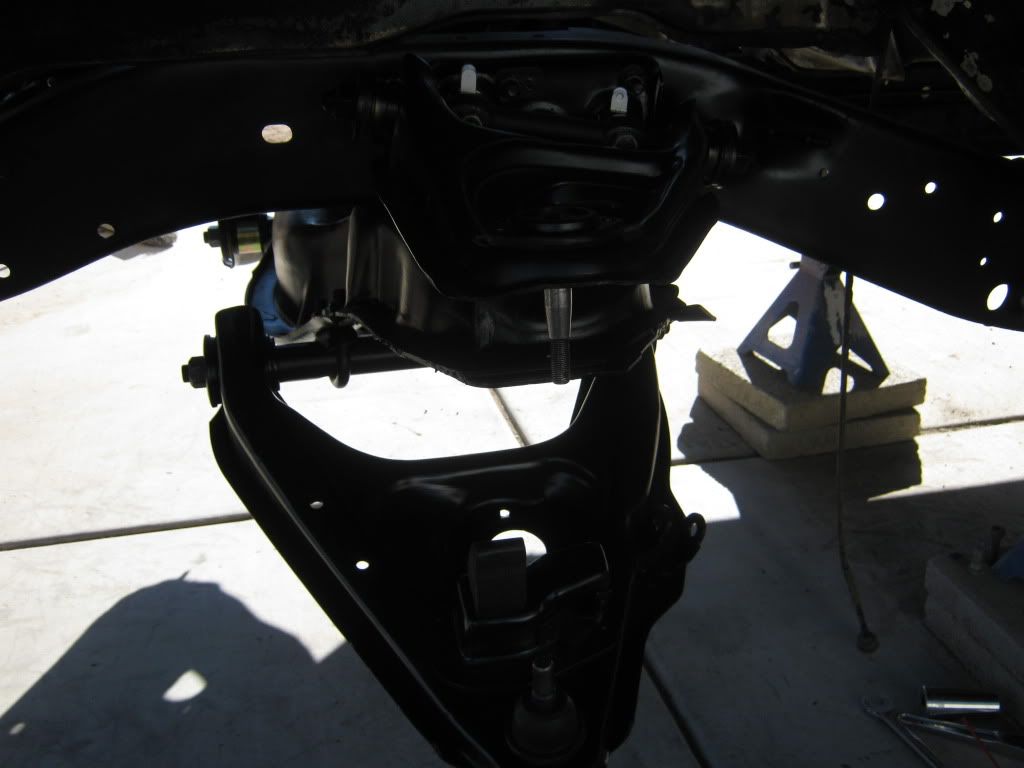 I'm not sure how much extra caster this mod will give me, but I think it will definitely be worth the effort. All told, I have right at $50 into this mod ($45 for the machine work, $5 for the nuts/bolts). I'm probably a couple of months away from being ready for the alignment shop, so I'll post up my results when I get them.
__________________
Check out my latest endeavor: https://roundsixpod.com My build threads: '55 Chevy: http://67-72chevytrucks.com/vboard/s...d.php?t=247512 '64 C-20: http://67-72chevytrucks.com/vboard/s...d.php?t=446527 Last edited by chevyrestoguy; 01-02-2012 at 03:19 PM. |

|

|
| Bookmarks |
|
|


 Threaded Mode