
|
Register or Log In To remove these advertisements. |
|
|
|
|||||||
|
|
Thread Tools | Display Modes |
 04-18-2010, 02:21 AM
|
#1 |
|
Senior Member
Join Date: Aug 2002
Location: Valley Center KS
Posts: 3,525
|
Gen 3 Drive By Wire cruise control HOW TO
This write up describes how to hook up a cruise control switch to a drive by wire (DBW) 5.3L engine.
My harness is from a 2004 silverado. Other vehicles should be similar, but you’ll want to verify your pin out numbering on the TAC module yourself. I used a turn signal with cruise control handle is from Digital Dakota “HND-3”. This allowed this handle to be installed onto my van tilt column. The problem that I later realized with this handle is the set/coast and resume/accelerate do not work as they should to be compatible with the GM wiring harness. There may be other handles that work with the GM harness, but I already had the Digital Dakota handle so I wanted to use it. Basically, I used two relays to change the signals from the handle from normally open to normally closed. It’s not quite as simple as that since the handle powers the “resume/accelerate” when you push the “resume accelerate” button as well as the “set/coast button”. But the relays account for this too. So here are the parts you need: Qty 1 Digital Dakota turn signal handle with cruise DAK-HND-3 Qty 2 Relays (I used PCO-5591PT since it included a connector to the relay)  Various butt and splice connectors and extra length of wires if needed Tools: Wire Stripping tool / crimp tool Test light Paint pen Wiring diagram of ECM and cruise circuit and this diagram: 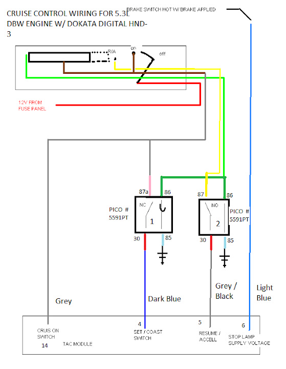 Step 1 Install the handle, ECM, and TAC modlule. All of my stuff was installed prior to hooking up the cruise control and the truck was running/driving great without it.  Step 2 Find a suitable location for the relays. I mounted mine to the same mount that my ECM and TAC module is mounted to, which is in the cab out of the weather. I used a couple of self tapping screws through the relay mounting holes into the sheet metal. Step 3 I numbered the relay connectors so I didn’t get confused with the paint pen. I also removed the wires not needed from each connector.  If you are using the same relays I used, remove the yellow wire from connector 1 (contact 87) and the pink/orange wire from connector 2 (contact 87a) 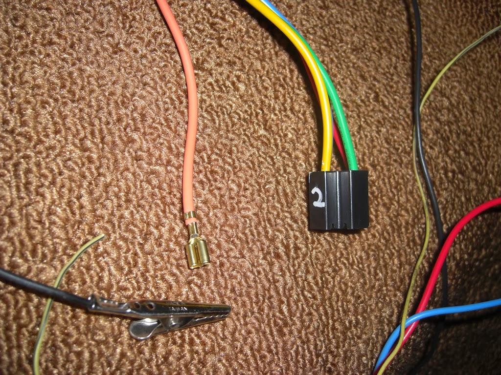 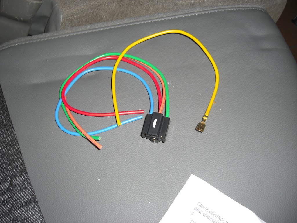 Step 4 Wire up the relays as shown in the attached wiring diagram but don’t connect the wires to the TAC module. I used a EZ brand wiring harness and it included a “cruise power” wire. I connect this to the red wire of the handle. The yellow wire of connector 2 to the yellow wire of the handle Both green wires to the green wire of the handle Pink wire of connector 1 to the brown wire of the handle Blue wires of each connector to ground 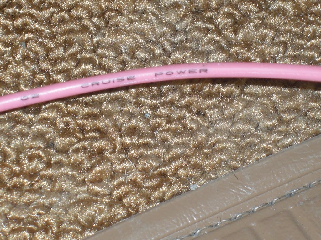 Step 5 Test your initial relay wiring with your test light. You will probably have to have your ignition switch on in order to power the cruise circuit. You want to verify that the brown/pink wire has power when you turn the switch to “on” Next, verify the red wire of connector 1 is hot when you push the “set/cruise” button on the end of the handle. Finally, verify the red wire of connector to is hot when you slide the slider on the handle to “resume/accelerate”. If these don’t check out, check your wiring and connections. 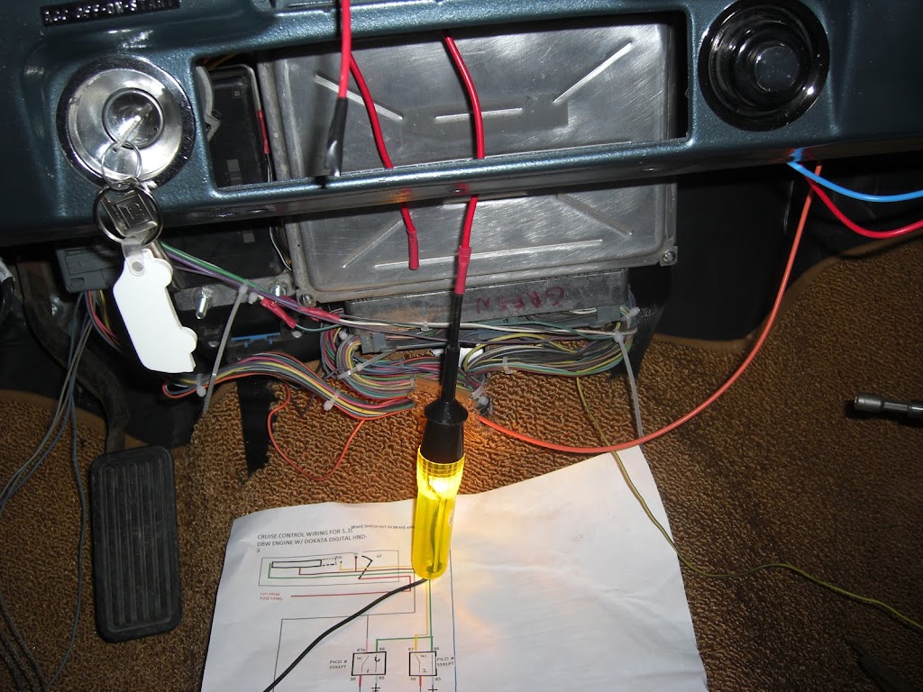 Step 6: Connect wires to TAC module Connect the brown/pink wire to pin 14 of the TAC module (Grey wire) Connect the red wire of connector 1 to pin 4 of the TAC module (Dark Blue wire) Connect the red wire of connector 2 to pin 5 of the TAC module (Grey/Black wire) 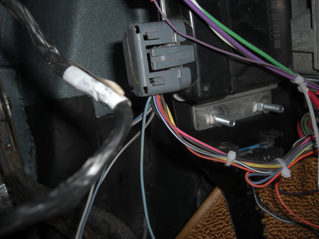 Step 7 One last connection There is one last wire from the TAC module that must be connected. It is a light blue wire from pin 6 of the TAC module. This wire connects to the brake switch wire that is hot only when the brakes are pushed. You’ll have to use your test light to determine which wire this is on your brake switch (especially if you are also running a transmission with a lockup converter) Not to hard to figure out, but this wire should be hot only when the brake pedal is pushed. This wire was labeled “brake switch” on my EZ wiring harness. Step 8 Test it out on the road Pretty much take out the vehicle and make sure all of the functions work. I suggest you take some tools with you and have your hand ready to turn off the ignition if something doesn’t work right as if you have not wired it up correctly there is a possibility of the cruise staying on and not being able to stop. If this happens, don’t panic, turn off your vehicle and pull over and figure out what you did wrong. Hopefully since we tested things in step 5 you won’t have a problem.
__________________
Project Bruiser: 68 Pro-Touring C-10 5.3L / 4L60E Project Ironhide: 97 GMC Crew Cab 4x4 Cummins SOLD: '69 GMC 1/2T SWB TBI'd: Project No Buck Assembly Manual Index Sign up Thread!!! Factory Service Manual Index Last edited by Ackattack; 04-18-2010 at 02:34 AM. |

|

|
| Bookmarks |
|
|


 Threaded Mode